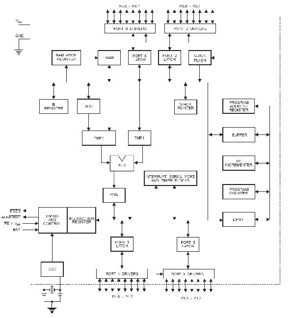
The micro-controller generic part number actually includes a whole family of microcontrollers that have numbers ranging from 8031 to 8751 and are available in N-channel Metal Oxide Silicon (NMOS) and CMOS construction. 89c52 is an 8-bit micro-controller having 40 pins arranged as DIP packages. The features unique to micro-controllers include:
I/O PORTS WITH PROGRAMMABLE PINS
- TIMERS AND COUNTERS
- SERIAL DATA COMMUNICATION
- 16-bit program counter and data pointer
- 8-bit stack pointer
- Internal ROM of 8k
- Internal RAM of 128 bytes
- Four register banks each containing eight registers
- 16 bytes addressable at the bit level
- 80 bytes of general purpose data memory
- 32 input/output pins arranged as four 8 bit ports
- Three 16-bit timer/counter
- Full duplex serial data receiver/transmitter
- Control registers: TCON, TMOD, SCON, PCON, IP and IE
- Two external and three internal interrupt sources
- Oscillator and clock circuits
|
Pin
|
Alternate Use
|
SFR
|
|
P3.0 – RXD
|
Serial data input
|
SBUF
|
|
P3.1 – TXD
|
Serial data output
|
SBUF
|
|
P3.2 – INT0
|
External interrupt 0
|
TCON.1
|
|
P3.3 – INT1
|
External interrupt 1
|
TCON.3
|
|
P3.4 – T0
|
External timer 0 input
|
TMOD
|
|
P3.5 – T1
|
External timer 1 input
|
TMOD
|
|
P3.6 – WR
|
External memory write pulse
|
|
|
P3.7 – RD
|
External memory read pulse
|
|
Timer mode 3:
Counting:
Interrupts:
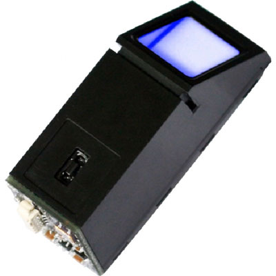
6.5V(exceeding this value will cause permanent damage to the module)
Search Time
<1.5s 200 fingerprint, average value in test
Tolerated Angle Offset
Communication Baud Rate:
|
3.2.6: EXAMPLES:
Add fingerprint:
|
|
|
|
Description: Add fingerprint at the designated position.
|
|
|
|
Length 3 bytes
|
|
|
|
Format?Command code 0x40 + high byte of the to-be-added fingerprint ID
|
+ low
|
|
|
byte of the to-be-added fingerprint ID.
|
|
|
For example:
Remarks
1. If fingerprint ID in the command is out of range, module will respond as parameter error:
For example
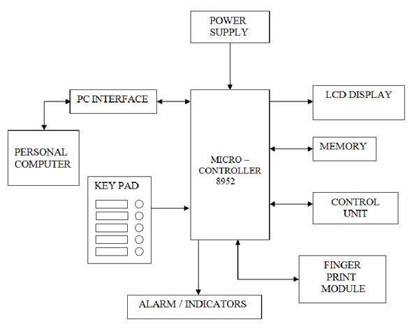
The LCD display panel is used to display status messages and error messages. DMC series is the name given to the dot matrix character LCD display modules that have been developed by Shenzhen Jing Handa Electronics Co., Ltd.
RS-232 is simple, universal, well understood and supported but it has some serious shortcomings as a data interface. The standards to 256kbps or less and line lengths of 15M (50 ft) or less but today we see high speed ports on our home PC running very high speeds and with high quality cable maxim distance has increased greatly. The rule of thumb for the length a data cable depends on speed of the data, quality of the cable. Electronic data communications between elements will generally fall into two broad categories: single-ended and differential. RS232 (single-ended) was introduced in 1962, and despite rumors for its early demise, has remained widely used through the industry. Independent channels are established for two-way (full-duplex) communications. The RS232 signals are represented by voltage levels with respect to a system common (power / logic ground). The “idle” state (MARK) has the signal level negative with respect to common, and the “active” state (SPACE) has the signal level positive with respect to common. RS232 has numerous handshaking lines (primarily used with modems), and also specifies a communications protocol
The RS-232 interface presupposes a common ground between the DTE and DCE. This is a reasonable assumption when a short cable connects the DTE to the DCE, but with longer lines and connections between devices that may be on different electrical busses with different grounds, this may not be true. RS232 data is bi-polar…. +3 TO +12 volts indicate an “ON or 0-state (SPACE) condition” while A -3 to -12 volts indicates an “OFF” 1-state (MARK) condition…. Modern computer equipment ignores the negative level and accepts a zero voltage level as the “OFF” state. In fact, the “ON” state may be achieved with lesser positive potential. This means circuits powered by 5 VDC are capable of driving RS232 circuits directly, however, the overall range that the RS232 signal may be transmitted/received may be dramatically reduced.
The output signal level usually swings between +12V and -12V. The “dead area” between +3v and -3v is designed to absorb line noise. In the various RS-232-like definitions this dead area may vary. For instance, the definition for V.10 has a dead area from +0.3v to -0.3v. Many receivers designed for RS-232 are sensitive to differentials of 1v or less.This can cause problems when using pin powered widgets – line drivers, converters, modems etc. These type of units need enough voltage & current to power them self’s up. Typical UART (the RS-232 I/O chip) allows up to 50ma per output pin – so if the device needs 70ma to run we would need to use at least 2 pins for power. Some devices are very efficient and only require one pin (some times the Transmit or DTR pin) to be high – in the “SPACE” state while idle.
Shown in circuit diagram tab 1.
Supply Section of this circuit consists of a 12 volts adaptor, and a IC 7805 IC. The output of the second regulator(IC 7805) is +5 volts, which is used for all other digital applications.
The RS232 IC got heated due to flow of reverse current to the circuit from the pc.
- We faced problem in setting baudrate for SM630 which operates at 57600 baudrate and later it was modified.
- SM630 responses in no time which the microcontroller is unable to read , so we used interrupts to store and then read the data as required.
- Memory of finger print module can be expanded .We can use a 1mb flash memory finger print module for increasing the capacity.
- External memory can be provided for storing the finger print image, which can be later accessed for comparison.
- Smart Card reader module is supposed to be introduced with the existing module for further security, and to reduce the database storage.
- Audio output can be introduced to make it user friendly for illiterate voters.
- Retina scanning can also be developed.
Circuit Diagrams
Filed Under: Electronic Projects

Questions related to this article?
👉Ask and discuss on Electro-Tech-Online.com and EDAboard.com forums.
Tell Us What You Think!!
You must be logged in to post a comment.