This circuit can sense the overload condition and breaks the power if the load increases above the set point. It is an ideal circuit to protect Uninterrupted Power Supply devices like Inverter.
Fig. 1: Image Of Power Supply Device(Inverter)
Let us see its working …
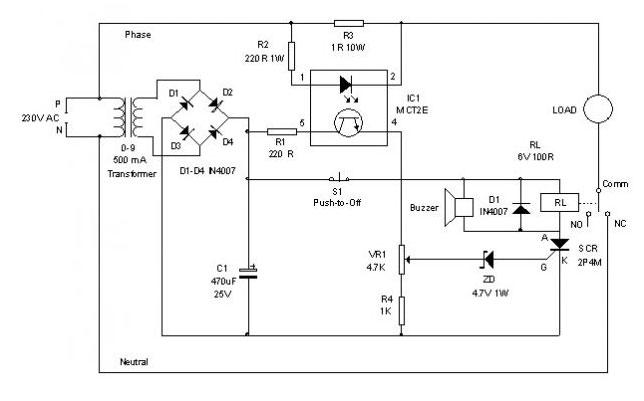
The Optocoupler MCT2E and the Resistor R3 (1 Ohm 10 Watts) will do the trick. The Optocoupler has an LED and a Phototransistor inside with connecting leads. The LED of MCT2E is connected parallel to the resistor R3 with a current limiter R2 for the LED. The phototransistor of Optocoupler is connected to the transformer derived 9 volt DC through the current limiter R1. The load is connected through the Common and NC contacts of the relay. So it will work normally at power on.
As the load switches on, current flows through R3 depending on the current drawingby the load. This changes the brightness of LED inside the Optocoupler which in turn control the biasing of the phototransistor. The emitter current of phototransistor thus depends on the brightness of LED which in turn depends on the current flowing through R3 to the load.
When the load current increases, a corresponding current flow increases through R3 and a corresponding potential difference develops across R3. When the load current increases maximum, Zener diode ZD conducts and triggers the SCR. The relay then turns on and breaks the supply to the load. When the relay turns on, the buzzer beeps to indicate the over load condition. The relay remains energized due to the latching action of SCR and it can be deenergized after removing the excess load and pressing S1.
How to Set?
To set the circuit for the desired tripping point, use 100 watts bulbs as load. If maximum,300 watts is the desired tripping point, use three 100 watts bulbs as load and slowly adjust VR1 till relay energize and lamps turn off. At this point, buzzer beeps. Then remove one bulb and reset using S1. Load will switch on normally. Again connect the bulb. When it switches on, the relay will cut the load. With the given value of R3, maximum load allowable is 500 watts. If this point is required, use a 500 watts bulb for calibration. Use a suitable 10 or 15 Amps relay to handle the load.
Caution: At some points like transformer Primary and relay contacts, Lethal voltage exists, so adequate precautionary measures must be taken while testing the circuit.
Circuit Diagrams
Filed Under: Circuit Design

Questions related to this article?
👉Ask and discuss on EDAboard.com and Electro-Tech-Online.com forums.
Tell Us What You Think!!
You must be logged in to post a comment.