How to detect Electronic Smog

Description

Table of Contents:

  1. How to detect Electronic Smog
  2. How to set?
  3. More about LM3914
Contributor: 
D.Mohankumar

Electrons are invisible to human eye then how can we see the electronic smog existing in our home. Is there any method to see them? Impossible, the only method is to capture the energy from it to activate a circuit for giving a visual indication. When you sit in front of a computer or television, you are being bombarded by harmful waves quietly emanating from it. Even if you turn off the device, your biomagnetic field is still bombarded 24 hours a day, 7 days a week by the EM radiations from power cables, electric and electronic instruments etc. These radiations of different frequencies exist in our environment as ‘Electronic Smog’. Extremely low frequencies waves (ELF) exist wherever electricity flows and radiate it from every electrical item in your environment. Let us try this circuit to give a visual indication of the electronic smog.
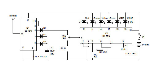
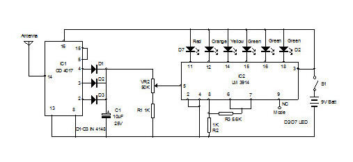
 
The input section of the circuit is the popular decade counter IC CD4017.It is the 5 stage divide by 10 Johnson decade counter with 10 decoded outputs. The counter advances on the positive edge of the clock signal in its input pin 14 when the clock enable pin 13 is at logic 0. The input of CD4017 is ultra sensitive and readily accepts the RF energy from the atmosphere. Thealternating electromagnetic field near the electric appliances acts as repeating pulses for the input of the IC. By receiving these pulses, IC1 gives high outputs. Out of the 10 outputs of IC1, only 3 outputs are used. These are connected to 3 diodes to give continuous input to IC2.Output 5 is shorted with the reset pin 15 so that when this output becomes high, IC resets and repeats the cycle. Capacitor C1 provides buffering action to the input of IC2. 

Electronic Smog Detector Circuit

Output from IC1 passes through VR2 to the input of IC2 LM 3914 which is a 10 output display driver. Only 6 outputs are used to drive LEDs as a meter.IC1 sinks currentand lights the LEDs one by one when the input receives an increment of 125 milli volts. Pin 18 sinks current first and pin10 last. LEDs do not require current limiting resistors since the LED current is programmed by the resistor connected to pin7 and pin8.Pin 9 is not connected to get a dot mode display. If it is connected to positive rail, bar mode display is obtained.