The rise in temperature level of a motor during its operation beyond a permissible limit is known as overheating. The causes of motor overheating are motor overloading, distortion in the supply voltage, impaired cooling capability, unbalanced supply voltages etc. Because of overheating, we can face the problems such as Electrical fire, Insulation failure, Decrease in life time of motor due to earlier wear and tear of the motor windings etc.Hence, for three phase induction motors, it is necessary that all the three phases of supply be present and the Motor Temperature be within the permissible limits. Hence, for the protection of the motors from mechanical damage and to increase its life time, it is very necessary to protect the phase motors from Single Phasing and Overheating.
In this project, We are going to design a hardware circuit to prevent the three phase loads from single phasing or overheating by disconnecting the load from the supply whenever any one of the two occurs, to monitor the current status of the motor by the help of LCD screen showing the current temperature and bulbs showing which phases are currently present, inform the user through alarm and by sending SMS to the user’s mobile whenever any one of the abnormal condition occurs.
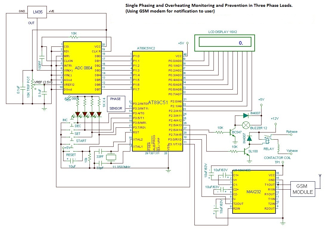
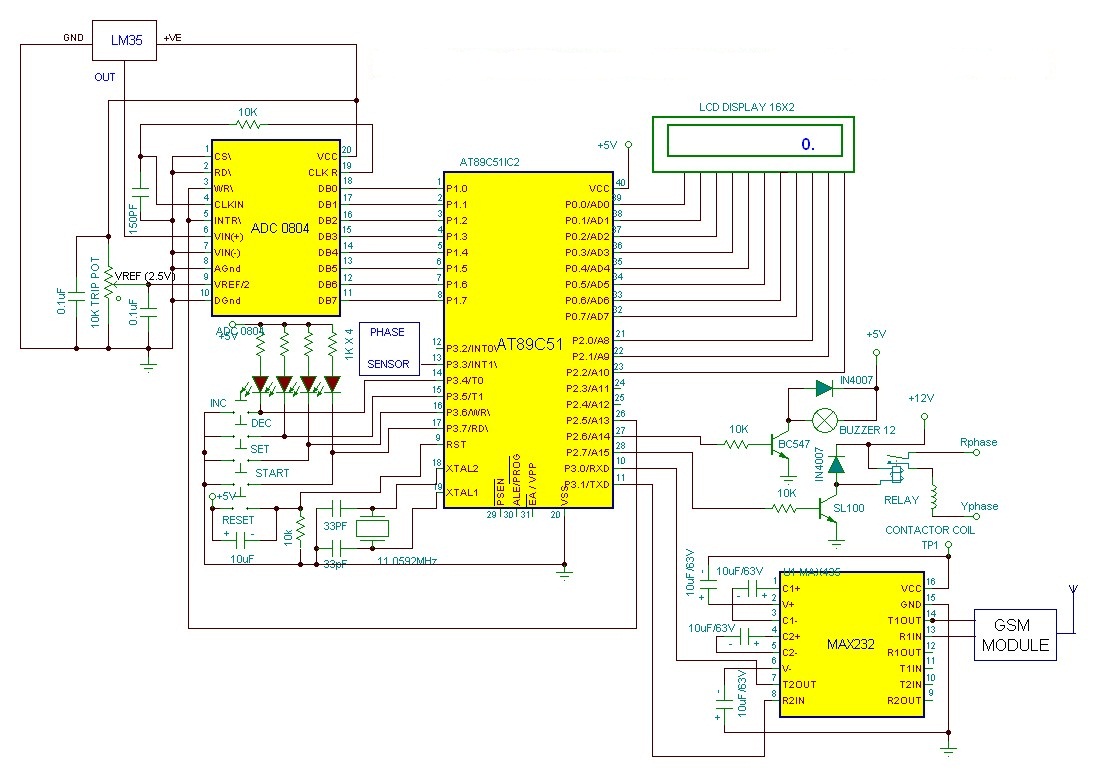
The hardware circuit makes the use of AT89C51 microcontroller to sense the abnormal condition i.e. single phasing or overheating and sound a buzzer and send SMS to the user’s mobile by the use of a GSM Modem and de-energize the 4-pole contactor which disconnects the load from the supply. Three single phase transformers are used in star connection whose primary is connected to the 3 phase supply. The secondary ends of 6V are connected in parallel, which produces net output voltage of 0 V whenever all phases are present and nearly 6 V when any one of the phase fails. The LM35 temperature sensor senses the motor temperature. The output of the temperaturesensor is analog signal. Hence, it is converted into Digital signal by using an Analog/Digital converter ADC 0804 and fed to the microcontroller. According to the motor class insulation, the hot spot temperature or the critical temperature of the motor can be set. The current motor temperature can be continuously monitored in the LCD screen. In case, if the motor temperature exceeds the hot spot or the critical temperature, the microcontroller buzzes an alarm, sends SMS and disconnects the supply from the load. Hence, as a real time application, this project finds it best place to be used in the Industries and various sectors to prevent the motor from the damages from Single Phasing and Overheating so as to improve the life expectancy of the motors and save the High cost machines from frequent failure and permanent damages
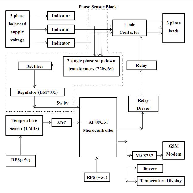
Block Diagram
This project, consist of the above blocks. It mainly consists of two major blocks. Temperature sensor and phase sensor block. The Phase sensor block is generally used to sense the Single Phasing and temperature sensor block is generally used to sense the overheating in the motors. In Phase sensor block, 3 single phase potential transformers are connected in star connection in the primary side and delta connection in the secondary side. The output of the delta connected transformers is again fed to the rectifier and regulator circuit. If all the phases are present, the output of the rectifier and regulator circuit is 5V, if not, it is 0V. Hence this 5V or 0V is fed to the AT89C51 microcontroller to control the relay connected to it. On the other hand, the temperature sensor senses the temperature of the motor. In case, if the temperature of the motor exceeds the set temperature of the motor, the microcontroller trips the relay and hence disconnects the load from the supply. The AT89C51 microcontroller block is interfaced with GSM module, LCD Display and Buzzer. If anyone of the two cases occurs, the GSM modem will send a message to the user’s mobile stating the present status of the motor and also sounds a buzzer. Hence, in this way, this circuit prevents the motor from the effects of overheating and single phasing. The elaborated description of the various blocks used in this project is summarized below.
Working
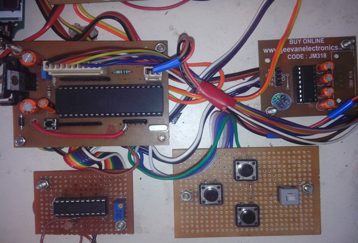
Microcontroller with Motor Start/Stop button
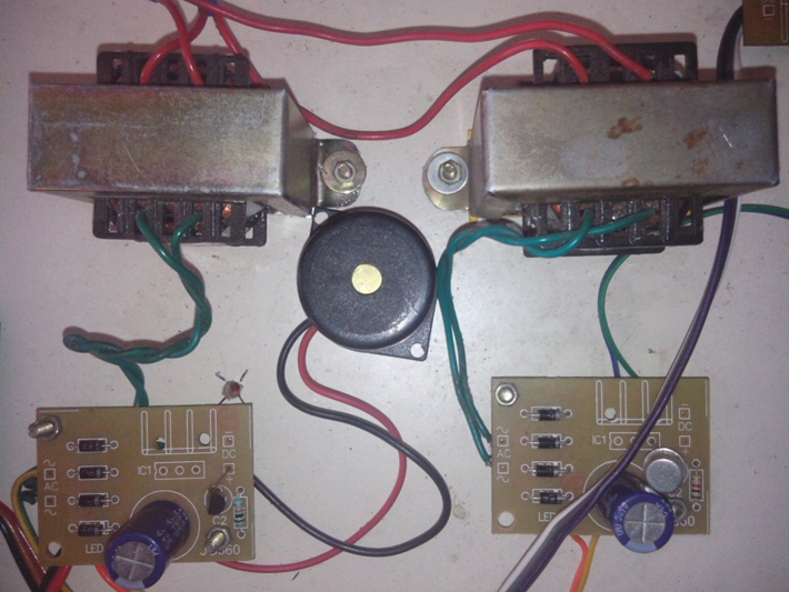 Regulated Power Supply
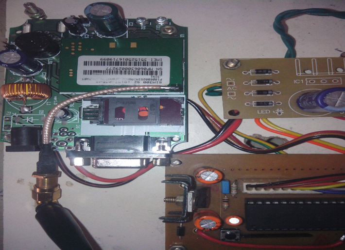
Microcontroller Interfaced with GSM Module
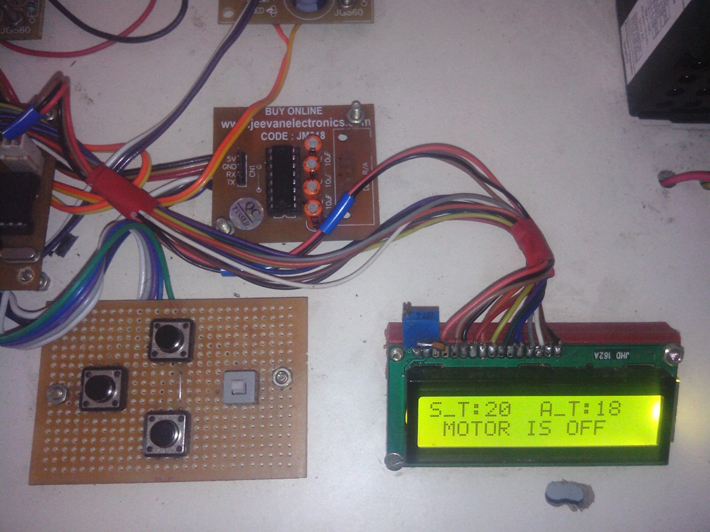
Screen Display when motor goes into OFF state as single phasing occurs
Way of Operation
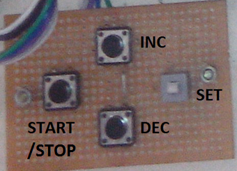
1.Press SET button and go on pressing the INC button to increase the Critical Temperature value of motor. E.g. 50ºC
2.We can use the DEC button to decrease the critical temperature value that we have set.
3.Then press SET button again
4.Press START/STOP button to start the motor.
5.If we want to stop the motor, we can press START/STOP button again.
6.In Display, we can view Actual Temperature and Set temperature.
7.If Actual temperature reaches the Set temperature, The contactor trips the motor, buzzer is alarmed and Send SMS to the user’s mobile.
8.If anyone of the three phases R,Y,B fails, same process happens.
9.Hence, we can save the motor from damage from Single phasing and Over heating
Conclusion
As aimed, using this project, we are able to protect the motor from the severe effects of single phasing and overheating during abnormal conditions. A buzzer is sounded whenever the abnormal condition occurs. The motor is disconnected from the three phase supply using contactor when anyone of the failure occurs. Furthermore, the user is notified about the single phasing or overheating condition by sending SMS using GSM modem. The critical temperature of the three phase load can be set as per our requirement and motor rating just by using a setting button in the microcontroller board. The program in the microcontroller can be changed as per our wish to change the message to be sent to the user during anyone of the abnormal problem.
Nearly one billion motors are used in several industries all over the world. All these motors are very costly and their protection is the must. Previously bimetallic strips and thermal protection relays were used to protect the motor from the effects of overheating. But by using this project, we can set the critical temperature of the motor, view the present temperature and variation of temperature at very instant as the temperature here is a digital data and is displayed continuously in the LCD screen. Moreover, previously, overvoltage protection relays were used in each phase to protect the motors from single phasing which is not a reliable method of protection for single phasing. So, in this project we were able to distinguish to problem of single phasing problem in accurate way, monitor the phase in which the phase failure occurred and protected the motor by disconnecting it from supply and notified the user by sending SMS to his mobile by using GSM module. Our future improvement for this project is to expand the project for commercial use in the industries. We are planning to achieve this by communicating the Microcontroller with the PC using wireless control scheme. Furthermore; software will be developed to display the temperature of the motor and the status of each and every motor running in the Industry. The software will also be used to set the critical temperature of the motors using PC and control the operation of each and every motor from the main computer whenever needed.
Project Source Code
###
#include <REG51.H>#include <stdio.h> /* standard I/O .h-file */#define LCD_data P0sbit logic = P3^3;sbit inc = P3^4;sbit dec = P3^5;sbit start = P3^6;sbit mtr = P3^7;sbit buz = P2^7;sbit relay = P2^6;sbit sc = P2^5;sbit RS = P2^0;sbit RW = P2^1;sbit EN = P2^2;void lcd_int();void lcd_cmd(int);void lcd_wr(unsigned char);void lcd_line1(unsigned char *str);void lcd_line2(unsigned char *str);void delayms(unsigned int);void sms(unsigned int);void hex_dec(unsigned char ,unsigned char );void main(){unsigned int track=0,temp=20,adc=0,f=1;P0=0;P2=0;P1=255;P3=255;lcd_int();lcd_line1("S_T:00 A_T:00");lcd_line2(" MOTOR IS OFF ");SCON = 0x50; /* SCON: mode 1, 8-bit UART, enable rcvr */TMOD |= 0x20; /* TMOD: timer 1, mode 2, 8-bit reload */TH1 = 0xfd; /* TH1: reload value for 2400 baud */TR1 = 1; /* TR1: timer 1 run */TI = 1; /* TI: set TI to send first char of UART */delayms(5);//inc=0;dec=0;start=0;mtr=0;sc=0;delayms(50);sc=1;//printf ("welcome");while(1){while(start==1){f=1;relay=0;lcd_line2(" MOTOR IS OFF ");if(inc==0){if(temp<=99){temp++;delayms(2);}}if(dec==0){if(temp>=0){temp--;delayms(2);}}adc=P1;hex_dec(temp,adc);}lcd_line2(" MOTOR IS OFF ");relay=0;adc=P1;hex_dec(temp,adc);f=1;if(mtr==0){lcd_line2(" MOTOR IS ON ");while(f==1){adc=P1;//adc=adc/3;relay=1;hex_dec(temp,adc);if(adc>=temp){relay=0;f=0;lcd_line2(" MOTOR IS OFF ");buz=1;delayms(100);buz=0;track=1;sms(track);}if(logic==0){relay=0;f=0;lcd_line2(" MOTOR IS OFF ");buz=1;delayms(100);buz=0;track=2;sms(track);relay=0;}if(start==1){f=0;}}}}//while(1)}void sms(unsigned int track){lcd_line2("sending sms.....");printf("ATn");delayms(100); // 2 sec delayprintf("AT+CMGF=1n");delayms(100); // 2 sec delayprintf("AT+CMGS="9994484510"n");delayms(100); // 2 sec delayif(track==1){printf("OVER TEMPERATUREn");printf("THREE PHASE OKn");printf("MOTOR IS IN OFF STATE");}if(track==2){printf("PHASE FAILUREn");printf("TEMPERATURE OKn");printf("MOTOR IS IN OFF STATE");}putchar(26); // transmit messagedelayms(100);delayms(100);}void delayms(unsigned int msec) // Function for delay{int i,j;for(i=0;i<msec;i++)for(j=0;j<1275;j++);}void lcd_cmd(int n){LCD_data = n;RS = 0;RW = 0;EN = 1;delayms(5);EN = 0;return;}///INTIAL///void lcd_int(){RS = 0;RW = 0;EN = 0;lcd_cmd(0x38);lcd_cmd(0x0E);lcd_cmd(0x01);lcd_cmd(0x06);lcd_cmd(0x0C);return ;}///DATE WRITE///void lcd_wr(unsigned char n){LCD_data = n;RS = 1;RW = 0;EN = 1;delayms(5);EN = 0;return ;}///LINE 1///void lcd_line1(unsigned char *str){lcd_cmd(0x80);while (*str != '�'){lcd_wr(*str);++str;}return;}///LINE 2///void lcd_line2(unsigned char *str){lcd_cmd(0xC0);while (*str != '�'){lcd_wr(*str);++str;}return;}///CONVERSION///void hex_dec(unsigned char temp,unsigned char adc){lcd_cmd(0x84);lcd_wr((temp/10)+48);lcd_wr((temp%10)+48);lcd_cmd(0x8c);lcd_wr((adc/10)+48);lcd_wr((adc%10)+48);}###
Circuit Diagrams
Filed Under: Electronic Projects

Questions related to this article?
👉Ask and discuss on EDAboard.com and Electro-Tech-Online.com forums.
Tell Us What You Think!!
You must be logged in to post a comment.