Engineers Garage

  • Electronic Projects & Tutorials
    • Electronic Projects
      • Arduino Projects
      • AVR
      • Raspberry pi
      • ESP8266
      • BeagleBone
      • 8051 Microcontroller
      • ARM
      • PIC Microcontroller
      • STM32
    • Tutorials
      • Sensor Series
      • Engineering Deep Dives
      • AI
      • ARDUINO Compatible Coding
      • Audio Electronics
      • Battery Management
      • Beginners Electronics Series
      • Brainwave
      • Digital electronics (DE)
      • Electric Vehicles
      • EMI/EMC/RFI
      • EVs
      • Hardware Filters
      • IoT tutorials
      • LoRa/LoRaWAN
      • Power Tutorials
      • Protocol
      • Python
      • RPI Python Programming
      • Sensors
      • USB
      • Thermal management
      • Verilog
      • VHDL
    • Circuit Design
    • Project Videos
    • Components
  • Articles
    • Tech Articles
    • Insight
    • Invention Stories
    • How to
    • What Is
  • News
    • Electronic Product News
    • Business News
    • Company/Start-up News
    • DIY Reviews
    • Guest Post
  • Forums
    • EDABoard.com
    • Electro-Tech-Online
    • EG Forum Archive
  • DigiKey Store
    • Cables, Wires
    • Connectors, Interconnect
    • Discrete
    • Electromechanical
    • Embedded Computers
    • Enclosures, Hardware, Office
    • Integrated Circuits (ICs)
    • Isolators
    • LED/Optoelectronics
    • Passive
    • Power, Circuit Protection
    • Programmers
    • RF, Wireless
    • Semiconductors
    • Sensors, Transducers
    • Test Products
    • Tools
  • Learn
    • eBooks/Tech Tips
    • Design Guides
    • Learning Center
    • Tech Toolboxes
    • Webinars & Digital Events
  • Resources
    • Digital Issues
    • EE Training Days
    • LEAP Awards
    • Podcasts
    • Webinars / Digital Events
    • White Papers
    • Engineering Diversity & Inclusion
  • Guest Post Guidelines
  • Advertise
  • Subscribe

PWM, PAM, PPM using IC 555

By Ashutosh Bhatt September 25, 2012

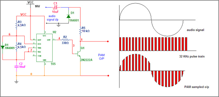
IC555 can be used to generate PAM with one NPN transistor connected at output. The chip is configured in astable mode to generate pulse train to get samples of information (audio) signal. Its frequency should be at least twice that of audio signal. Usually it is 8 KHz (because audio signal is up to 3.4 KHz) but for better quality here I am keeping it 32 KHz. This pulse train output is fed to base of NPN transistor. The collector of transistor is coupled with low frequency audio (information) signal through positive clamper made up of capacitor C1 and diode D1. The positive clamper will shift the level of audio signal above 0 V. The output at the collector of transistor is PAM wave. The amplitude of pulses generated by IC555 varies in accordance with the instantaneous amplitude of information signal.
 
Pulse-Amplitude-Modulation-(PAM).jpg
 
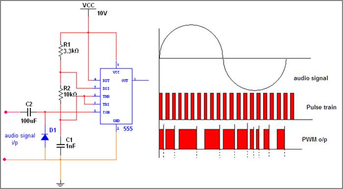
Pulse Width Modulation (PWM) using IC 555
If we apply variable voltage at control input (pin 5) of IC555 in astable mode then the width of output pulse will change accordingly. When we apply low frequency audio signal to the control input, internally the control voltage will change the reference voltage of comparator so charging time of capacitor changes every time and so width of o/p pulse also changes. So here as shown in figure the audio signal is applied at the control input through positive clamper circuit. The values of R1, R2 and C1 are chosen to generate pulse train of around 64 KHz. The width of o/p pulse will change in accordance with the amplitude of audio signal as shown in figure in Circuit Diagram 1tab.
 
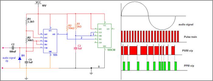
Pulse Position Modulation (PPM) using IC 555

PPM is simply PWM + monostable multi-vibrator. Means if we fed the PWM output to trigger input of IC555 in monostable mode then the output of monostable will be PPM wave. So to generate PPM we require one astable multi-vibrator to generate PWM signal and one monostable multi-vibrator to get desire PPM. The final circuit and the waveforms are as shown in Circuit Diagram 2 tab.


Project Source Code


Circuit Diagrams

Pulse-Width-Modulation-PWM
Pulse-Position-Modulation-PPM


Filed Under: 555 Timers, Electronic Projects
Tagged With: 555 timer circuit, pam, ppm, pwm
 

Next Article

← Previous Article
Next Article →

Questions related to this article?
👉Ask and discuss on Electro-Tech-Online.com and EDAboard.com forums.


Tell Us What You Think!! Cancel reply

Log in to leave a comment:

Lost your password?

Don't have an account? Register here

Submit a Guest Post

submit a guest post

EE TECH TOOLBOX

“ee
Tech Toolbox: Sensors
In this Tech Toolbox, we cover some of those technologies driving the next generation of connected systems, including ultra-low-power sensing strategies that extend node battery life, and 60 GHz CMOS radar for contactless health and presence detection.

EE Learning Center

EE Learning Center
“engineers
EXPAND YOUR KNOWLEDGE AND STAY CONNECTED
Get the latest info on technologies, tools and strategies for EE professionals.

HAVE A QUESTION?

Have a technical question about an article or other engineering questions? Check out our engineering forums EDABoard.com and Electro-Tech-Online.com where you can get those questions asked and answered by your peers!


RSS EDABOARD.com Discussions.

  • Solenoid AC Magnetic field water pump
  • how RS-485 transmits and receive logic levels between two MCUs
  • what is missing from this circuit?
  • x86 vs. ARM: Architecture Differences and Application Scenarios
  • Analyses and design of LDO

RSS Electro-Tech-Online.com Discussions

  • What is the most suitable light source for making a book light like this?
  • How charging is done in Transformer Inverters
  • extracting material properties from open load resonance
  • Oshon Basic, programing IF statements
  • USBASP Programming problems

Featured Tutorials

Learn - VHDL Tutorials (22 Part)

  • VHDL Tutorial – 11: Designing half and full-subtractor circuits
    VHDL Tutorial – 11: Designing half and full-subtractor circuits
  • VHDL Tutorial – 12: Design a 8-bit parity generator and circuit checker
    VHDL Tutorial – 12: Design a 8-bit parity generator and circuit checker
  • VHDL tutorial 13: Design 3×8 decoder and 8×3 encoder using VHDL
    VHDL tutorial 13: Design 3×8 decoder and 8×3 encoder using VHDL
  • VHDL Tutorial 14: Design 1×8  demultiplexer and 8×1 multiplexer using VHDL
    VHDL Tutorial 14: Design 1×8  demultiplexer and 8×1 multiplexer using VHDL
  • VHDL Tutorial 17: Design a JK flip-flop (with preset and clear) using VHDL
    VHDL Tutorial 17: Design a JK flip-flop (with preset and clear) using VHDL
  • VHDL Tutorial 18: Design a T flip-flop (with enable and an active high reset input) using VHDL
    VHDL Tutorial 18: Design a T flip-flop (with enable and an active high reset input) using VHDL
More Tutorials >

Recent Articles

  • Navitas launches isolated TO-247 package for SiC
  • 3D scanning: How photogrammetry is reshaping digital engineering
  • EPC launches 3-phase GaN motor-drive boards
  • TDK launches 30 nH DC-link capacitors
  • Amphenol RF launches 40 GHz solderless connectors

EE ENGINEERING TRAINING DAYS

engineering
Engineers Garage
  • Analog IC TIps
  • Connector Tips
  • Battery Power Tips
  • EDABoard Forums
  • EE World Online
  • Electro-Tech-Online Forums
  • EV Engineering
  • Microcontroller Tips
  • Power Electronic Tips
  • Sensor Tips
  • Test and Measurement Tips
  • 5G Technology World
  • Subscribe to our newsletter
  • About Us
  • Contact Us
  • Advertise

Copyright © 2026 WTWH Media LLC. All Rights Reserved. The material on this site may not be reproduced, distributed, transmitted, cached or otherwise used, except with the prior written permission of WTWH Media
Privacy Policy

Search Engineers Garage

  • Electronic Projects & Tutorials
    • Electronic Projects
      • Arduino Projects
      • AVR
      • Raspberry pi
      • ESP8266
      • BeagleBone
      • 8051 Microcontroller
      • ARM
      • PIC Microcontroller
      • STM32
    • Tutorials
      • Sensor Series
      • Engineering Deep Dives
      • AI
      • ARDUINO Compatible Coding
      • Audio Electronics
      • Battery Management
      • Beginners Electronics Series
      • Brainwave
      • Digital electronics (DE)
      • Electric Vehicles
      • EMI/EMC/RFI
      • EVs
      • Hardware Filters
      • IoT tutorials
      • LoRa/LoRaWAN
      • Power Tutorials
      • Protocol
      • Python
      • RPI Python Programming
      • Sensors
      • USB
      • Thermal management
      • Verilog
      • VHDL
    • Circuit Design
    • Project Videos
    • Components
  • Articles
    • Tech Articles
    • Insight
    • Invention Stories
    • How to
    • What Is
  • News
    • Electronic Product News
    • Business News
    • Company/Start-up News
    • DIY Reviews
    • Guest Post
  • Forums
    • EDABoard.com
    • Electro-Tech-Online
    • EG Forum Archive
  • DigiKey Store
    • Cables, Wires
    • Connectors, Interconnect
    • Discrete
    • Electromechanical
    • Embedded Computers
    • Enclosures, Hardware, Office
    • Integrated Circuits (ICs)
    • Isolators
    • LED/Optoelectronics
    • Passive
    • Power, Circuit Protection
    • Programmers
    • RF, Wireless
    • Semiconductors
    • Sensors, Transducers
    • Test Products
    • Tools
  • Learn
    • eBooks/Tech Tips
    • Design Guides
    • Learning Center
    • Tech Toolboxes
    • Webinars & Digital Events
  • Resources
    • Digital Issues
    • EE Training Days
    • LEAP Awards
    • Podcasts
    • Webinars / Digital Events
    • White Papers
    • Engineering Diversity & Inclusion
  • Guest Post Guidelines
  • Advertise
  • Subscribe