Summary:
This article will give information about how Arduino ADC can be used to get the data from DHT11 Humidity and Temperature sensor and to transfer it over the CAN bus using CAN controller MCP2515. It will give you an in-depth idea about SPI interface with Arduino and CAN controller and Commands used for the configuration of CAN Communication.
Description:
Prerequisites & Equipment:
You are going to need the following:
-
Two Arduino Board or Arduino clone(Here is a guide if you need)
-
A 5v TTL -UART Bluetooth module.
-
LCD and DHT11 Sensor.
-
Arduino IDE for the programming.
-
Two CAN Tranciever.
The Controller Area Network (CAN) is a Serial, Asynchronous, Multi-master communication protocol for connecting electronic control modules in Automotive and industrial applications. Can have as many features like Low cost, Easy to implement, peer to peer Network with powerful Error Checking, Higher Transmission Rates 1MBitps.
This project is designed to read Humidity and Temperature using DHT11 And transmitting by CAN protocol implementation. The Humidity and Temperature changes are measured by the ADC and transmitted to the other node using the CAN Bus and the data is received at the other node and displayed in an LCD.
It is assumed that the reader has gone through the Getting started with CAN interface with Arduino and done all the things discussed in it.

Fig. 1: Typical image of DHT-11 Temperature and Humidity Sensor with Pin Numbers
The block diagram of the project is shown in Figure. The system is made up of two CAN nodes. DISPLAY node that reads the temperature from the CAN Bus and displays it on an LCD. This process is repeated continuously. The other node called COLLECTOR node reads the temperature an humidity from DHT11 temperature sensor.

Fig. 2: Block Diagram of Arduino to Arduino CAN Communication Prototype
The DISPLAY Processor:
DISPLAY processor consists of an Arduino with a MCP2515 CAN module and an TJA1040 transceiver chip. The Microcontroller is operated from a 16MHz crystal. And MCP2515 has an SPI interface which is used to connect using SPI pins in Arduino. The Pins CANH and CANL of the transceiver chip are connected to the CAN bus. LCD is connected to Arduino to display the temperature values.
The COLLECTOR Processor:
The COLLECTOR processor consists of an Arduino with a MCP2515 CAN module and an TJA1040 transceiver chip.The DHT11 is chosen because it is lab calibrated, accurate and stable and its signal output is digital. The DHT11 is a basic, ultra low-cost digital temperature and humidity sensor. It uses a capacitive humidity sensor and a thermistor to measure the surrounding air, and spits out a digital signal on the data pin (no analog input pins needed). It’s fairly simple to use, but requires careful timing to grab data. The only real downside of this sensor is you can only get new data from it once every 2 seconds, so when using our library, sensor readings can be up to 2 seconds old.
Pin Name Description
1 VDD Power supply 3 – 5.5 V DC
2 DATA Serial data output
3 NC Not connected
4 GND Ground
Wiring:
Connect the sensor to the Arduino as shown below
DHT11 Arduino
Pin 1 Vcc
Pin 2 Analog0( And a 10K pull up resistance)
Pin 4 Gnd
Install the DHT11 library and Modify:
Download this zipped file and unzip it under the libraries directory of the Arduino IDE folder. For example, for my computer’s setup, the directory is
XXXarduino-1.0.1libraries
After copying files across, the directory
XXXarduino-1.0.1librariesDHT
should have the following two files: dht.h and dht.cpp
Program:
Load the program dht11.ino after you save it onto your computer and open it in Arduino IDE .
Running the program:
Reading Temperature and Humidity data and transmitting it in the CAN Bus:
Load the program TX.ino after you save it onto your computer and open it in Arduino IDE .
-
Compile the program in the Arduino IDE
Temperature and Humidity values can be get by the following commands using the DHT library.
float h = dht.readHumidity();
float t = dht.readTemperature();
The following function is used to send the values to the can bus. Detailed instruction can be found here.
CAN.sendMsgBuf(0x70,0, 2, stmp);
Receiving CAN data and displaying in an LCD:
Load the program RX.ino after you save it onto your computer and open it in Arduino IDE .
-
Compile the program in the Arduino IDE
The following function is used to receive the values from the CAN bus and to display on an LCD. Detailed instruction can be found here.
CAN.readMsgBuf(&len, buf);
Loading software for Arduino:
If you are new to Arduino you can start with here. You have to start with the Arduino IDE (Integrated Development Environment) from Arduino . Download the code from below link and upload it to the Arduino board.
Hardware assembly:

Fig. 3: Prototype of Arduino based Receiver Circuit designed on breadboard

Fig. 4: Prototype of Arduino to Arduino CAN Interface communicating Ambient temperature
Fig. 5: Image showing CAN Bus connections with receiver side Arduino circuit

Fig. 6: Image showing DHT-11 Temperature and Humidity Sensor Interfaced to Arduino Transmitter Circuit on one side of CAN Bus
Make the circuit as is given by the circuit diagram. Make the circuit with your selected parts and connect the motors to the circuit.
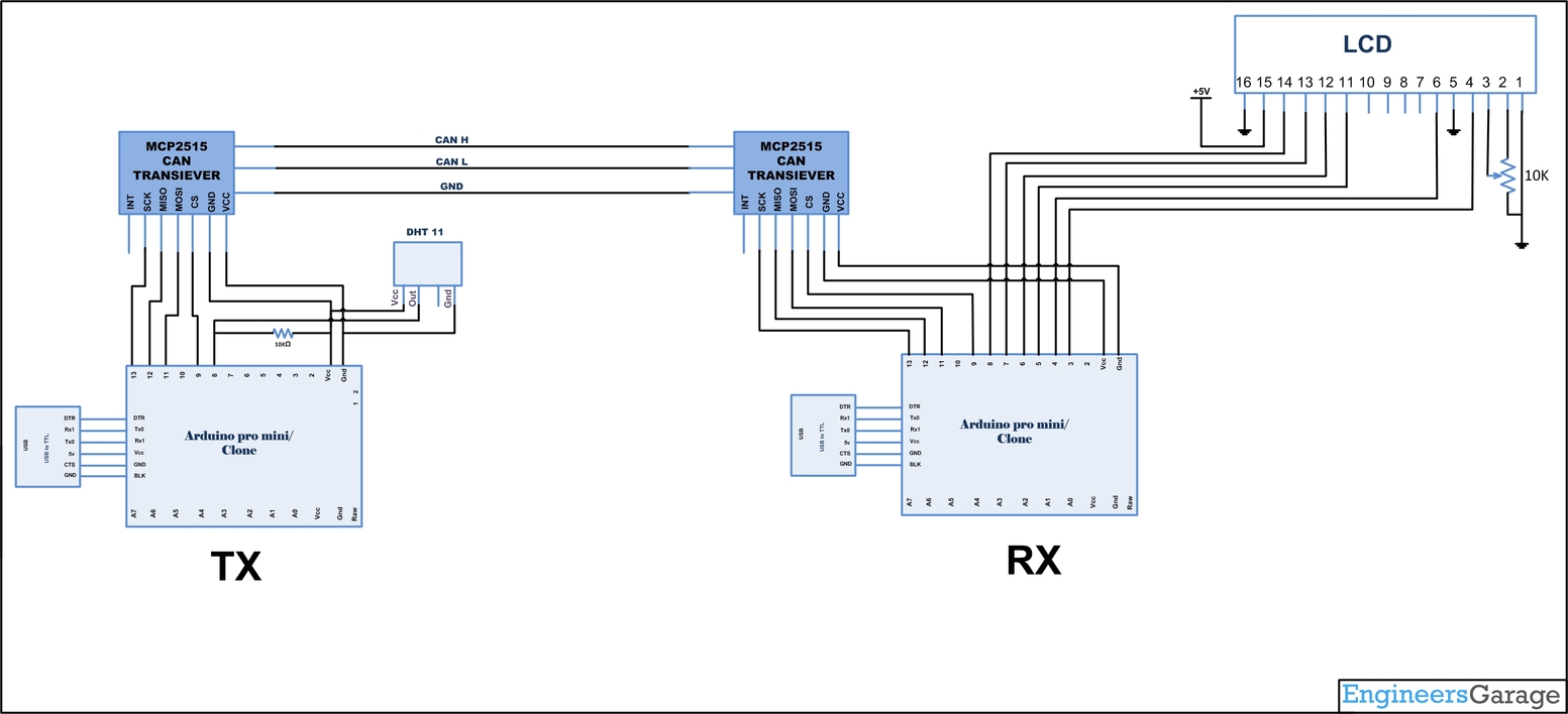
Circuit Diagrams
Project Video
Filed Under: Electronic Projects
Filed Under: Electronic Projects

Questions related to this article?
👉Ask and discuss on EDAboard.com and Electro-Tech-Online.com forums.
Tell Us What You Think!!
You must be logged in to post a comment.