Engineers Garage

  • Electronic Projects & Tutorials
    • Electronic Projects
      • Arduino Projects
      • AVR
      • Raspberry pi
      • ESP8266
      • BeagleBone
      • 8051 Microcontroller
      • ARM
      • PIC Microcontroller
      • STM32
    • Tutorials
      • Audio Electronics
      • Battery Management
      • Brainwave
      • Electric Vehicles
      • EMI/EMC/RFI
      • Hardware Filters
      • IoT tutorials
      • Power Tutorials
      • Python
      • Sensors
      • USB
      • VHDL
    • Circuit Design
    • Project Videos
    • Components
  • Articles
    • Tech Articles
    • Insight
    • Invention Stories
    • How to
    • What Is
  • News
    • Electronic Product News
    • Business News
    • Company/Start-up News
    • DIY Reviews
    • Guest Post
  • Forums
    • EDABoard.com
    • Electro-Tech-Online
    • EG Forum Archive
  • DigiKey Store
    • Cables, Wires
    • Connectors, Interconnect
    • Discrete
    • Electromechanical
    • Embedded Computers
    • Enclosures, Hardware, Office
    • Integrated Circuits (ICs)
    • Isolators
    • LED/Optoelectronics
    • Passive
    • Power, Circuit Protection
    • Programmers
    • RF, Wireless
    • Semiconductors
    • Sensors, Transducers
    • Test Products
    • Tools
  • Learn
    • eBooks/Tech Tips
    • Design Guides
    • Learning Center
    • Tech Toolboxes
    • Webinars & Digital Events
  • Resources
    • Digital Issues
    • EE Training Days
    • LEAP Awards
    • Podcasts
    • Webinars / Digital Events
    • White Papers
    • Engineering Diversity & Inclusion
    • DesignFast
  • Guest Post Guidelines
  • Advertise
  • Subscribe

0 – 99 Counter Using IC 4026

By Anjali Sethiya May 21, 2013


This circuit can be used in various projects where we require the counting. Like in doctors’ clinic or hospitals, in restaurants, in customer care offices where long queue is there and we want to stop the rush at the counter. This system is very effective where man power is less. In this you have to provide a token to the person and the person has to wait for its turn which can be displayed on the 7 segment display. With the help of this counter circuit we can maintain the silence and the person will also be informed about their turn.

This circuit is based on 4026, a Johnson counter IC commonly used in digital display. It has a 5 stage Johnson decade counter with decoder which convert the Johnson code to a 7 segment decoded output. This means it will convert the input into numeric display which can be seen on 7 segment display. It can be used for displaying analogue value, such as temperature with pic microcontroller, used for counting objects. It can be used in various applications like in 7 segment decimal display circuit, in clocks, timer etc. Advantage of 4026 counter–

   * It contains counter and 7 segment decoding in one package.

  *  It can be easily interface with 7 segment types.

  *  Ideal for low power display.

  *  Operated at wide range of temperature from 5V to 20V.

  *  The big advantage of the 4026B counter IC is that it can drive a 7-segment display without eeding a decoder driver IC


Description

To understand its working how we can interface 4026 with 7 segment display, first have to  look on its pin diagram –


4026 IC


Now let us understand the working of individual pins-

1. Pin 1 or clock pin- It receives clock signals, and at every positive clock and  counter advances one by one. You can provide clock with the switch, 555 timer or with the help of logic gates. In short high pulse on this input increments the counter.


2. Pin 2 or disable clock (clk inhibit) pin- 4026 counter advances one by one by receiving positive pulse at this time for this clock inhibit pin should be grounded. If it is connected to supply than counter advancement will be inhibited means there will be no meaning of clock pulse.


3. Pin 3 or enable display (En in) pin- It enable the 7 segment display to display the numeric value. It should be kept high for enabling the display. Mean output goes high when only when display enable is high.


4. Pin 4 or enable out- It Enables the carry out pin. In our circuit we have left this pin unconnected.


5. Pin 5 or divide by 10 output- It is used to complete one cycle for every 10 clock input cycle and it also used to cascade more IC’s.


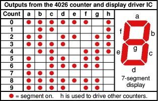
6.Pin 6, pin7 and Pin9 to pin 13 – These are 7 decoded output from a to g used to illuminates the corresponding segment of 7 segment display to display the digit from 0 to 9.


7. Pin 14 or not 2 output (UNGATED “C” SEGMENT) signals- They are not gated by the Display clock and therefore are available continuously. This feature is a requirement in implementation of certain divider function such a as divide by 60 and divide by 12.


8. Pin 15 or Reset pin- It is used to reset the counter. When it receives high it clears the counter and counting again starts from zero. One important thing reset pin should again made low to start the counter once again.


9. Pin 8 or ground pin and Pin 16 known or Vdd it should be connected to power supply.


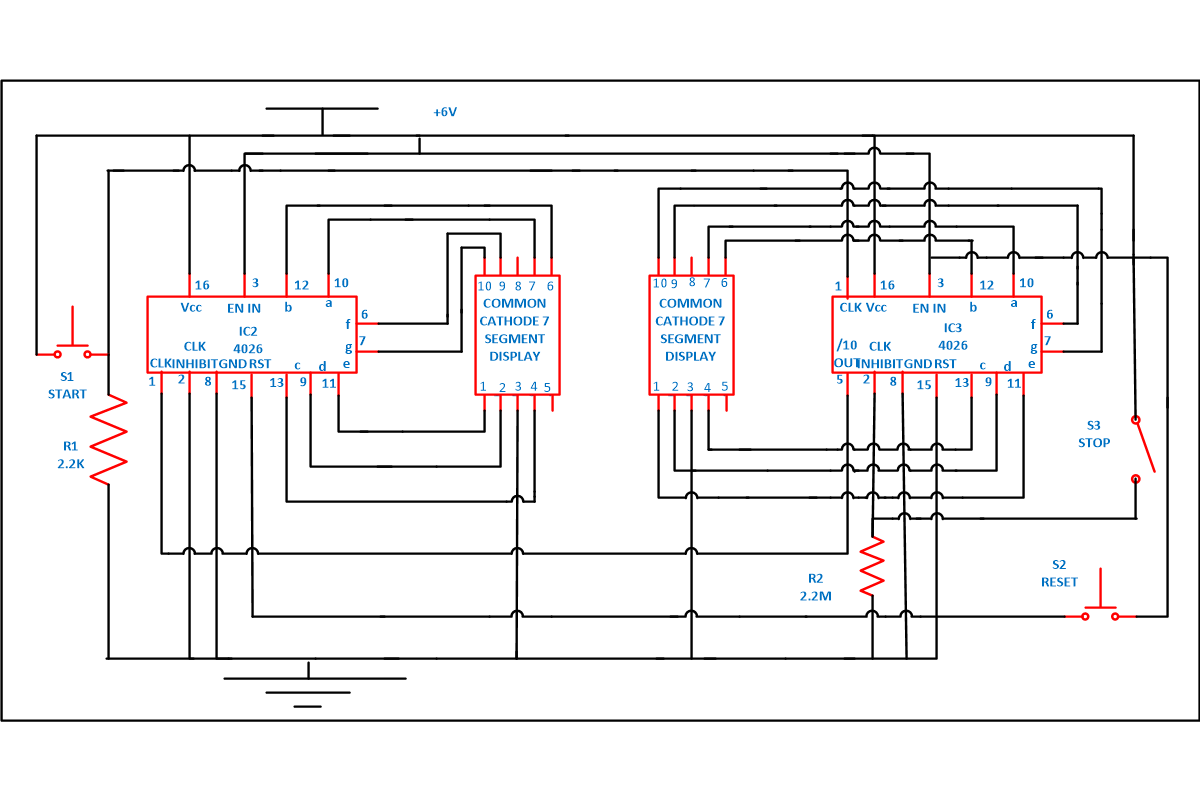
To understand its working assemble the circuit as shown in circuit diagram –


Johnson Counter Circuit

It uses a 4026 combined counter and display driver IC which is designed to drive 7 segment display. When you press the switch S1 counter starts from zero and it advances one each time whenever pin 1 receives a positive pulse. When you press the switch for first time numeric 1 will display. Then you again press the switch numeric 2 will display, giving you second output. In similar manner 3 and 4 will display. When count reaches to 9 after that it again starts it counting from zero.


For resetting the counter to zero at any point press switch S2. For this pin 15 must be taken high and then taken low again.  The table below shows sequence of how each segment glows after receiving clock signal.

 Working

Working of the counter circuit–

99 Counter

Assemble the circuit properly. Connect the pin 3 of both the IC 1 and 2 to supply, to on the display. If pin 3 is connected to ground we will get a blank display on 7 segment output.

And also connect the pin 15 which is a reset pin of the both the IC together so that when counting reaches to 99 it will reset the counter to zero. When you on the switch S3 counter will not progress irrespective of clock signal at pin 1 because this is connected to pin 2 that is disable clock (clk inhibit) pin and it goes high when it is on . As 4026 counter advances one by one by receiving positive pulse at this time clock inhibit pin should be grounded.

Now whenever a customer arrives in restaurant, hospital or customer care office, you can provide them with token number. Now apply power supply. Zero will be displayed on both the 7 segment display. As soon as switch S1 is pressed, a clock pulse is provided to pin 1 (which is a clock input pin) of IC1. After receiving the clock pulse 4026 IC counter advances and 1 will be displayed on common cathode 7 segment display. When second customer enters, same phenomenon occurs till count reaches 9. When it reaches 9 one cycle is completed. As you can see from circuit diagram pin 5 of IC1 is connected to pin 1 of IC2 to cascade another IC, after every 10th pulse it will go high to provide a clock pulse to IC2 to advance its counter that’s why we will receive a 1 on 7 segment common cathode display 2 .

Provide switch S1 and S3 to doctor or chef so that when they are done with one patient or customer they can press the switch and the next customer can go. Now people can see their number on display and go according to their token number.

Unit place number are displayed on display 1 and tens place numbers are displayed on display 2.  After completion of each cycle tens place advances one. Now you can cascade more 4026 IC to increase the number of display according to your requirements.  Play around it by adding and removing some more components. So now  can start your own project.

Video


Circuit Diagrams

0-99-Counter-usinf-4026


Filed Under: Electronic Projects
Tagged With: circuit, johnson counter
 

Next Article

← Previous Article
Next Article →

Questions related to this article?
👉Ask and discuss on EDAboard.com and Electro-Tech-Online.com forums.


Tell Us What You Think!! Cancel reply

You must be logged in to post a comment.

EE TECH TOOLBOX

“ee
Tech Toolbox: Internet of Things
Explore practical strategies for minimizing attack surfaces, managing memory efficiently, and securing firmware. Download now to ensure your IoT implementations remain secure, efficient, and future-ready.

EE Learning Center

EE Learning Center
“engineers
EXPAND YOUR KNOWLEDGE AND STAY CONNECTED
Get the latest info on technologies, tools and strategies for EE professionals.

HAVE A QUESTION?

Have a technical question about an article or other engineering questions? Check out our engineering forums EDABoard.com and Electro-Tech-Online.com where you can get those questions asked and answered by your peers!


RSS EDABOARD.com Discussions

  • Will this TL084C based current clamp circuit work?
  • ADS optimization cockpit window does not open
  • Voltage mode pushpull is a nonsense SMPS?
  • How to determine the maximum PAD frequency ?
  • Xiaomi Mijia 1C Robot problem of going backwards while working

RSS Electro-Tech-Online.com Discussions

  • Curved lines in PCB design
  • using a RTC in SF basic
  • PIC KIT 3 not able to program dsPIC
  • Siemens large industrial PLC parts
  • Parts required for a personal project

Featured – RPi Python Programming (27 Part)

  • RPi Python Programming 21: The SIM900A AT commands
  • RPi Python Programming 22: Calls & SMS using a SIM900A GSM-GPRS modem
  • RPi Python Programming 23: Interfacing a NEO-6MV2 GPS module with Raspberry Pi
  • RPi Python Programming 24: I2C explained
  • RPi Python Programming 25 – Synchronous serial communication in Raspberry Pi using I2C protocol
  • RPi Python Programming 26 – Interfacing ADXL345 accelerometer sensor with Raspberry Pi

Recent Articles

  • AC-DC power supply extends voltage range to 800 V DC
  • Infineon’s inductive sensor integrates coil system driver, signal conditioning circuits and DSP
  • Arm Cortex-M23 MCU delivers 87.5 µA/MHz active mode
  • STMicroelectronics releases automotive amplifiers with in-play open-load detection
  • Convection-cooled power controller integrates EtherCat connectivity

EE ENGINEERING TRAINING DAYS

engineering

Submit a Guest Post

submit a guest post
Engineers Garage
  • Analog IC TIps
  • Connector Tips
  • Battery Power Tips
  • DesignFast
  • EDABoard Forums
  • EE World Online
  • Electro-Tech-Online Forums
  • EV Engineering
  • Microcontroller Tips
  • Power Electronic Tips
  • Sensor Tips
  • Test and Measurement Tips
  • 5G Technology World
  • Subscribe to our newsletter
  • About Us
  • Contact Us
  • Advertise

Copyright © 2025 WTWH Media LLC. All Rights Reserved. The material on this site may not be reproduced, distributed, transmitted, cached or otherwise used, except with the prior written permission of WTWH Media
Privacy Policy

Search Engineers Garage

  • Electronic Projects & Tutorials
    • Electronic Projects
      • Arduino Projects
      • AVR
      • Raspberry pi
      • ESP8266
      • BeagleBone
      • 8051 Microcontroller
      • ARM
      • PIC Microcontroller
      • STM32
    • Tutorials
      • Audio Electronics
      • Battery Management
      • Brainwave
      • Electric Vehicles
      • EMI/EMC/RFI
      • Hardware Filters
      • IoT tutorials
      • Power Tutorials
      • Python
      • Sensors
      • USB
      • VHDL
    • Circuit Design
    • Project Videos
    • Components
  • Articles
    • Tech Articles
    • Insight
    • Invention Stories
    • How to
    • What Is
  • News
    • Electronic Product News
    • Business News
    • Company/Start-up News
    • DIY Reviews
    • Guest Post
  • Forums
    • EDABoard.com
    • Electro-Tech-Online
    • EG Forum Archive
  • DigiKey Store
    • Cables, Wires
    • Connectors, Interconnect
    • Discrete
    • Electromechanical
    • Embedded Computers
    • Enclosures, Hardware, Office
    • Integrated Circuits (ICs)
    • Isolators
    • LED/Optoelectronics
    • Passive
    • Power, Circuit Protection
    • Programmers
    • RF, Wireless
    • Semiconductors
    • Sensors, Transducers
    • Test Products
    • Tools
  • Learn
    • eBooks/Tech Tips
    • Design Guides
    • Learning Center
    • Tech Toolboxes
    • Webinars & Digital Events
  • Resources
    • Digital Issues
    • EE Training Days
    • LEAP Awards
    • Podcasts
    • Webinars / Digital Events
    • White Papers
    • Engineering Diversity & Inclusion
    • DesignFast
  • Guest Post Guidelines
  • Advertise
  • Subscribe