Engineers Garage

  • Projects and Tutorials
    • Electronic Projects
      • 8051
      • Arduino
      • ARM
      • AVR
      • PIC
      • Raspberry pi
      • STM32
    • Tutorials
    • Circuit Design
    • Project Videos
    • Components
  • Articles
    • Tech Articles
    • Insight
    • Invention Stories
    • How to
    • What Is
  • News
    • Electronic Products News
    • DIY Reviews
    • Guest Post
  • Forums
    • EDABoard.com
    • Electro-Tech-Online
    • EG Forum Archive
  • Digi-Key Store
    • Cables, Wires
    • Connectors, Interconnect
    • Discrete
    • Electromechanical
    • Embedded Computers
    • Enclosures, Hardware, Office
    • Integrated Circuits (ICs)
    • Isolators
    • LED/Optoelectronics
    • Passive
    • Power, Circuit Protection
    • Programmers
    • RF, Wireless
    • Semiconductors
    • Sensors, Transducers
    • Test Products
    • Tools
  • EE Resources
    • DesignFast
    • LEAP Awards
    • Oscilloscope Product Finder
    • White Papers
    • Webinars
  • EE Learning Center
  • Women in Engineering

Graphical lcd (128×64) Pin out, working and interface

By EG Projects

In this tutorial I am going to teach you the working and pin out of 128×64 graphical lcd. There are lot of graphical lcds available in the market. Each perform exactly the same function with some variations. Some are small in size and some bigger. Some are black and white and some multicolored. Some perform few numbers of operations and some can perform many functions. For example the graphical lcd you see on your mobile phone is different from the one in your car. 

Difference between graphical and ordinary lcds.

Graphical Lcd Rows(64) and Coulombs(128)Graphical Lcd Rows(64) and Coulombs(128)

Graphical lcds are different from the ordinary character lcds, like 16×1 16×2 16×4 20×1 20×2 etc. They (ordinary) can print\display only characters or custom made characters. They display characters in a fixed size matrix normally 5×7  or  5×8. Where as in graphical lcd’s e.g 128×64 we have 128×64=8192 dots or 8192/8=1024 pixels. We can display a character in a size which we need. More over we can make  a picture on a graphical lcd as well. If the size of graphical lcd is 1024 pixels we can display a picture on it covering 1024 pixels. More over we can also display video(animated or doted) an  video on graphical lcds.

Normally graphical lcd which is easily available in the market and is best to getting start in the field of graphical lcds is 128×64. It has 128 coulombs and 64 rows. You can display your data in 128×64 dot matrix. 


Graphical Lcd controller

Graphical lcd(128x64) PagesGraphical lcd(128×64) Halfs

Graphical  lcd is controlled by two KS0108 controllers. A single KS0108 controller is capable of controlling 4096 dots or 512 pixels. So for controlling a graphical lcd we need two KS0108 controllers.

Lcd is further divided in to two equal half’s. First half from 1 to 64 coulombs in controlled by first KS0108 controller. The second KS0108 controls the second half from 64 to 128 coulombs. The figure on the left explains about how the controller’s are dedicated for half’s.


Further graphical lcd half’s division

Each half is further divided in to 8 pages of equal sizes. Each page size is 8 rows and 64 coulombs. Each page contains 8*64=512 dots or 512/8=64 pixels. 

Graphical Lcd(128x64) Pages

Graphical Lcd(128×64) Pages

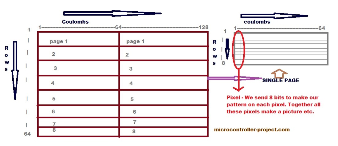
Page distribution in Pixels

Graphical Lcd(128x64) PixelGraphical Lcd(128×64) Pixel

Each page contains 64 pixels(64 coulombs and 8 rows). You can create your desired output on these pixels. Each pixel lights up when it is 0 and becomes off when it is 1.  Each pixel contains 8 dots. 

The figure on the left shows a single pixel of graphical lcd. Each pixel is built up by 8 dots. 1 coulomb and 8 rows constitute a pixel.


Graphical Lcd (128×64) Pinout

Picture

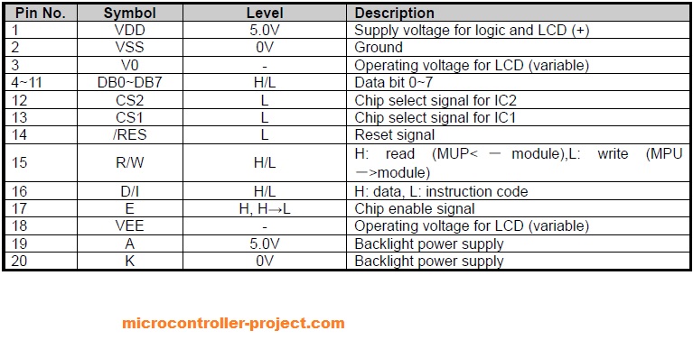
Graphical Lcd  pins are same as other character lcds. Only two new pins are introduced with the graphical lcd. These are CS1 and CS2. CS1 is chip select 1 it selects the first half or first KS0108 controller of lcd. CS2 is chip select 2 it selects the second half or second KS0108 controller of lcd. Both CS1 and CS2 are active low. By active low I mean for selecting a first or second half, make its associated pin (CS1 , CS2) low 0. All the other pins E (enable) R/W (read/write) RS or D/I (register select) works in the same way like for normal lcds.

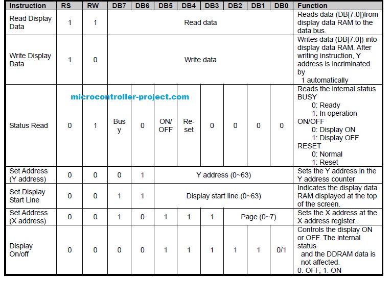
Like other lcds we also first have to initialize graphical lcd. By initializing I mean in which format we want to use our lcd. Like which half I want to use. Which page of which half I want to use. What is my x-address? What is my y-address?

Picture

Graphical Lcd Interfacing with 89c51
Graphical Lcd Interfacing with Pic16f877
​Displaying Images on 128×64 Graphical LCd
  • Display On/Off Display data appears when D is 1 and disappears when D is 0.Though the data is not on the screen with D=0, it remains in the display data RAM.Therefore, you can make it appear by changing D=0 into D=1.
  • Set Address (Y Address)Y-address is the pixel address. An address is set by instruction and increased by 1 automatically by read or write operations of display data.
  • Set Page (X Address) X-address is the page address.X address of the display data RAM is set in the X address register.Writing or reading to or from MPU (microcontroller) is executed in the specified page until the next page is set.
  • Write Display Data Writes data (D0~D7) into the display data RAM. After writing instruction, Y address is increased by 1 automatically.
  • Read Display Data Reads data (D0~D7) from the display data RAM.After reading instruction, Y address is increased by 1 automatically.
  • Display Start Line (Z Address) Z address (AC0~AC5) of the display data RAM is set in the display start line register and displayed at the top of the screen.


Graphical lcd Pinout and Working

Filed Under: Featured Contributions
Tagged With: 128x64, description, graphical lcd, pinout
 

Questions related to this article?
👉Ask and discuss on EDAboard.com and Electro-Tech-Online.com forums.


Tell Us What You Think!! Cancel reply

You must be logged in to post a comment.

HAVE A QUESTION?

Have a technical question about an article or other engineering questions? Check out our engineering forums EDABoard.com and Electro-Tech-Online.com where you can get those questions asked and answered by your peers!


Featured Tutorials

  • Adjustable 0 to 30V 2A DC Power Supply Circuit (Part 1/13)
  • Adjustable +/- 1.25V to +/-22V 1A Power Supply Circuit (Part 2/13)
  • Adjustable 0 to 15V 1A Mini Power Supply (Part 3/13)
  • Constant 12V Power Supply for LED Circuits (Part 4/13)
  • Constant +/-9V DC Symmetrical Power Supply Circuit (Part 5/13)
  • Making a Circuit Breaker (Part 6/13)

Stay Up To Date

Newsletter Signup

Sign up and receive our weekly newsletter for latest Tech articles, Electronics Projects, Tutorial series and other insightful tech content.

EE Training Center Classrooms

“ee

“ee

“ee

“ee

“ee

“ee

Recent Articles

  • STMicroelectronics introduces new single-channel load switches
  • STMicroelectronics and Microsoft to streamline development of secure IoT devices
  • Microchip adds to its 8-bit PIC and AVR microcontroller family
  • Infineon offers Press Pack IGBT for transmission and distribution applications
  • STMicroelectronics outlines path to $20B+ revenue

Most Popular

5G 555 timer circuit 8051 ai Arduino atmega16 automotive avr dc motor display Electronic Part Electronic Parts Fujitsu ic infineontechnologies integratedcircuit Intel IoT ir lcd ldr led maximintegratedproducts microchip microchiptechnology Microchip Technology microcontroller microcontrollers mosfet motor powermanagement Raspberry Pi remote renesaselectronics Research robot samsung semiconductor sensor software STMicroelectronics switch Technology vishayintertechnology wireless

RSS EDABOARD.com Discussions

  • Pls help me with these errors of my code
  • Space Vector PWM Help Needed
  • Carry-Lookahead Circuit Design VIVADO
  • could calibre lvs do not check mosfet B term
  • Mahindra Inverter continuous beep sound and all led glowing except battery indicator

RSS Electro-Tech-Online.com Discussions

  • Relaxation oscillator with neon or...
  • High component count for long delay circuit (inrush resistor switch out)
  • DIY Mini 12v Router UPS malfunction
  • MOSFET gets hot and burns
  • Positive and negative sides of voltage source
Engineers Garage
  • Analog IC TIps
  • Connector Tips
  • DesignFast
  • EDABoard Forums
  • EE World Online
  • Electro-Tech-Online Forums
  • Microcontroller Tips
  • Power Electronic Tips
  • Sensor Tips
  • Test and Measurement Tips
  • 5G Technology World
  • About Us
  • Contact Us
  • Advertise

Copyright © 2022 WTWH Media LLC. All Rights Reserved. The material on this site may not be reproduced, distributed, transmitted, cached or otherwise used, except with the prior written permission of WTWH Media
Privacy Policy | Advertising | About Us

Search Engineers Garage

  • Projects and Tutorials
    • Electronic Projects
      • 8051
      • Arduino
      • ARM
      • AVR
      • PIC
      • Raspberry pi
      • STM32
    • Tutorials
    • Circuit Design
    • Project Videos
    • Components
  • Articles
    • Tech Articles
    • Insight
    • Invention Stories
    • How to
    • What Is
  • News
    • Electronic Products News
    • DIY Reviews
    • Guest Post
  • Forums
    • EDABoard.com
    • Electro-Tech-Online
    • EG Forum Archive
  • Digi-Key Store
    • Cables, Wires
    • Connectors, Interconnect
    • Discrete
    • Electromechanical
    • Embedded Computers
    • Enclosures, Hardware, Office
    • Integrated Circuits (ICs)
    • Isolators
    • LED/Optoelectronics
    • Passive
    • Power, Circuit Protection
    • Programmers
    • RF, Wireless
    • Semiconductors
    • Sensors, Transducers
    • Test Products
    • Tools
  • EE Resources
    • DesignFast
    • LEAP Awards
    • Oscilloscope Product Finder
    • White Papers
    • Webinars
  • EE Learning Center
  • Women in Engineering