1) Introduction
Requirement Analysis
Components Required
Signal Conditioning Process
Project Source Code
Project Source Code
###
#include<reg51.h>
sbit ale=P2^1; //address latch enable
sbit oe=P2^0; //output enable
sbit sc=P2^2; //start conversion
sbit eoc=P2^7; //end of conversion
sbit ADD_A=P1^1; // Address pins for selecting input channels.
sbit ADD_B=P1^2;
sbit ADD_C=P1^3;
sfr addr_port=0x90; //p1 por
sfr data_port=0x80; //p0 port
unsigned char k, data_buffer;
void transmit();
void delay(unsigned int count);
void transmit() //serial port transmission
{
SBUF=k;
while(TI==0);
TI=0;
SBUF=data_buffer;
while(TI==0);
TI=0;
}
void delay(unsigned int count) // Function to provide time delay in msec.
{
int i,j;
for(i=0;i<count;i++)
{
for(j=0;j<1275;j++);
}
}
void main()
{
data_port=0xFF;
delay(2);
ale=0;
oe=0;
sc=0;
TMOD=0x20;
TH1=0xFD; //timer1 setting for serial communication
SCON=0x50;
TR1=1;
while(1)
{
for(k=0; k<=15; k++)
{
addr_port=k;
delay(2);
ale=1;
delay(2);
sc=1;
delay(1);
ale=0;
delay(1);
sc=0;
while(eoc==1);
while(eoc==0);
oe=1;
data_buffer=data_port;
transmit();
delay(2);
oe=0;
}
if (k==15)
{
k=0;
}
}
}
###
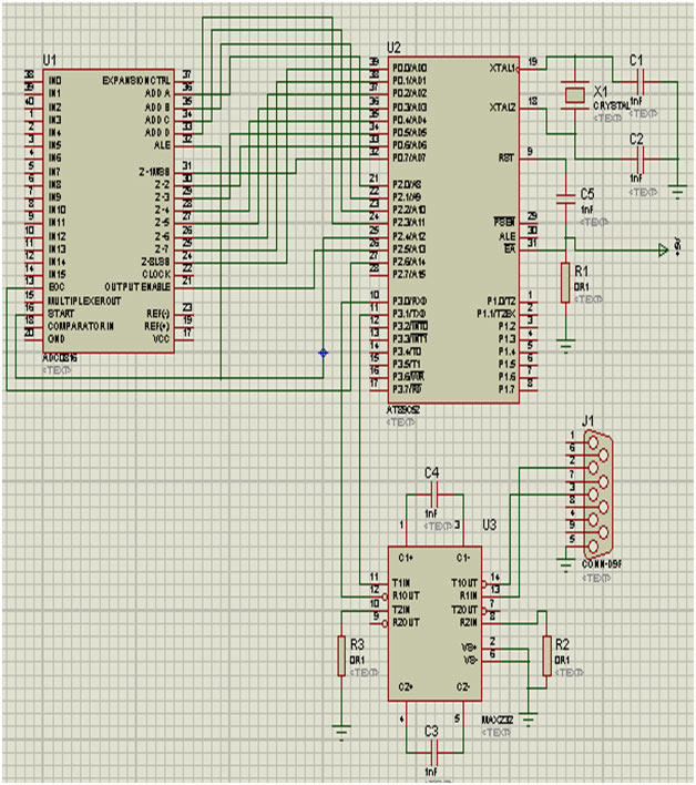
Circuit Diagrams
Filed Under: Electronic Projects

Questions related to this article?
👉Ask and discuss on Electro-Tech-Online.com and EDAboard.com forums.
Tell Us What You Think!!
You must be logged in to post a comment.