“Scientists investigate that which already is; Engineers create that which has never been”- Albert Einstein

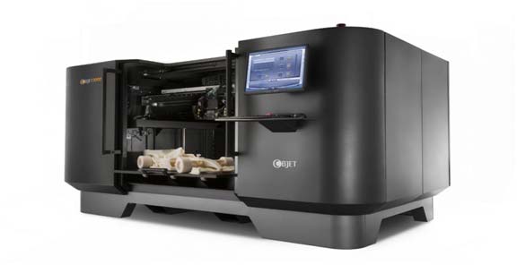
Fig. 1: Picture a Typical 3D Printer
Have you ever had an idea of a design lingering in your head, but couldn’t possibly bring it into reality considering the manufacturing or economic limitations? Have you ever lost or damaged a part of a product which is no longer available in the market? Are you an inventor looking to produce working models to test functionality?Well, these are some of the questions now a days, to which the utilization of a 3D-Printer would be the recommended solution. So what exactly is 3D Printing, how does it work?
What is 3D Printing?
Intense global competition has pushed manufacturing firms to apply new technologies which allowed them to push out products faster, more accurately and with lower labor dependence into the markets which not only satisfies customer requirements faster, but also at a cheaper prices.
3D printing is a computer aided, additive manufacturing process in which a solid part is created from its CAD (Computer Aided Design) model. Sometimes this process is referred to as a ‘freedom manufacturing’ process thanks to its dynamic and flexible classes of applications. The CAD model produced by 3D modelling software applications such as CATIA, Solidworks, Pro-Engineer, UG, etc. is first sliced into layers by various other software applications. The 3D printer then produces the cross section of the part and stacks it layer by layer to produce the finished real world replica of the intended CAD model. 3D printing has been known to maintain a cycle time reduction between 30%-90% depending on the technology used and the complexity of the part.
The 3D Printing Process

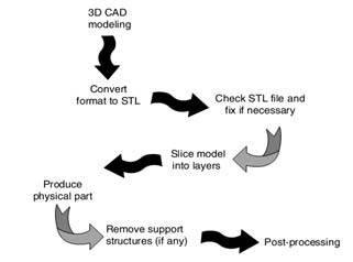
Fig. 2: Image Repesenting Basic Data Flow Involved in 3D Printing
The figure above represents a basic data flow of the processes involved in 3d printing
The 3d model can be obtained by two ways, one is generated by any CAD system as either a surface model or a solid model. The other way is by obtaining 3d models from an existing physical part using scanners such as CMMs (Co-ordinate Measurement Machines), by a process called Reverse Engineering.
The standard format of input to the printing hardware is the STL (STereoLithographic) format file which converts the 3d model into a shell consisting of a mesh of triangles joined by common sides and vertices. These triangles describe the X, Y and Z co-ordinates of the surface giving a path to the hardware.
Closely spaced 2D cross sections are created from the 3D STL filewith predefined thicknesses depending upon the fineness required (typically about 0.006 inches). This leads to a staircase formation and affects the final surface finish.
Support structures are added to hold the part together after the part is completed. Post completion, the support structures are melted off or dissolved in solvents.
Now that we’ve looked into the software and general data flow process, let’s look at the physical methods by which the part is fabricated.
Methods of 3D Printing
Based on the initial state of the material, the types of 3d printing may be broadly classified as liquid based, solid based and powder based.
Liquid based 3d printers consists of its initial material in the liquid state. Liquid based processes contain the advantage of having a good surface finish since the liquid initially has a smooth surface. Usually liquid based 3d printers use a heat source such as UV laser to solidify the liquids, which are mostly photo sensitive epoxy resins. This process of phase change occurring in the resins is called ‘curing’. The UV laser is concentrated on each point to control the curing process. The point location is coordinated with the point data received from the sliced STL file. The most common liquid based process (also called photo polymerization printing) is the Stereo Lithography process (SLA)
i. Stereo Lithography Apparatus (SLA)

Fig. 3: Stereo Lithography Apparatus
This is one of the earliest technologies to be used as a prototyping technique and was patented by scientist and engineer Chuck Hull in 1986. It consists of a vat of photopolymer resin on a movable platform which moves in the Z-direction (up and down). The UV laser cures the 2D layer producing the cross section. After one layer is completed, the platform moves down by the Z-thickness value to fabricate the next layer. Therefore the X-Y coordinates actuate the UV laser whereas the Z coordinate is controlled by the platform. The UV light causes the photopolymer to harden exactly at the point where the light contacts the surface. The photopolymers can be epoxies, vinyl ethers or acrylates. The finished part is rinsed and support parts removed either manually or by heating. The resolution and accuracy of the finished part is very close to the CAD model and the engineering drawings guaranteeing companies to supply their best product in the least time possible. Industrial applications include the sectors of aerospace, automotive, armaments, consumer electronics, medical and surgical equipment, toys and many other large scale production sectors. The limitations of this process is the inability to form hollow or enclosed features which may cause liquid to be trapped inside.
The SLA process although it being a success in mass production and large scale industries, are very expensive for the small scale and personal home based applications. A more commercialized method of the liquid based 3D printing process is the Inject based liquid process (Objet Polyjet by Objet Geometries ltd.) which combines the SLA with material jet printing. A thin layer of photopolymer resin is sprayed onto a tray which is simultaneously exposed to a UV laser curing source. Sometimes instead of a heating source, a cooling source can cause the solidification (water cooled to ice), which is the case of the Rapid Freeze Prototyping Process.
ii. Extrusion Based Processes (Solid Phase)

Fig. 4: Extrusion Based 3D Printing Process
In the solid based printing process, a solid wire is fed which is melted into a shape to form a shape. A specific process called Fused Deposition Modelling (FDM) was developed by the Advanced Ceramics Research (ACR) in Tucson, Arizona, USA and developed further by a leading 3D modelling industry, Stratasys Inc., of Minneapolis, Minnesota. The FDM process uses engineering grade thermoplastics such as ABS (Acrylonitrile Butadiene Styrene). The wire filament is pre heated and extruded out finely to build the layer from the bottom up. The extrusion head is shown in the figure below. The drive wheels force the wire from the spool through the nozzle which is surrounded by heating coils. Similar to the SLA it has a moving platform which is at a lower temperature to ensure rapid hardening of the solid from liquid phase. The nozzle controls the X-Y axes movement while the platform in the Z-axis. Multiple nozzles maybe present so that support materials can be simultaneously added to the part. The obvious advantages include the production of non-delicate and toughparts with low wastage of material. The support material used is water soluble and can be removed easily. The accuracy may not be up to the standard of the SLA due to shrinkage on cooling.
iii. Laminated Object Manufacturing (LOM)

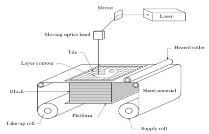
Fig. 5: Diagram Showing 3D Printing Through Laminated Object Manufacturing
Some of the other solid based processes include contour cutting where layers of material are added onto a platform where they are cut by a laser as per the profile. This process is commercially known as Laminated Object Manufacturing (LOM) which was developed by Helisys Inc. in 1985. In this process a Ribbon of sheet metal or plastics with thickness equal to that of the layers of the sliced STL file, rolls out to a laser beam which cuts out the cross section on the sheetvia a heated roller. The waste material is separated and rolled out from the part. Since LOM does not involve any phase change, there are no shrinkages and heat defects.
iv. Selective Laser Sintering (SLS – Powder Based Printing)

Fig. 6: Diagram Showing Selective Laser Sintering 3D Printer
Selective laser sintering is a powder based printing process which was patented in 1989. In SLS, a laser is used to bond powdered material into a solid object (a process known as sintering). A fine grained powder is used in this process which can be a mixture of different materials or a single material having thermoplastic properties. The main advantage of this process includes the fact that the mechanical properties can be altered as per our liking by mixing different powders of fixed compositions. A laser sinters the powders one layer after the other with the layers being leveled after each layer is completed. This process is very much similar to the stereolithography in the sense that the liquid in SLA is replaced by powder in the SLS but using a similar laser based heating source.
v. 3D Inject Printing Process

Fig. 7: Diagrammic Figure of 3D Inject Printer
The 3D inject printing process is the most affordable technologies in the present market. It was developed by the Massachusetts Institute of Technology, USA (MIT) in 1993. It is an inexpensive process which solidifies powders by the use of a liquid binder. It replaces the laser in the SLS with liquid binders and the standard inkjet printing technology. Its working can be compared to a standard 2D printer which we use in our homes. Instead of printing on a sheet of paper, the liquid binder is sprayed onto a thin layer of powder according to the 3D CAD data from the STL file. The powder needs to be distributed accurately and evenly on the platform. This is done by a roller and a feed piston as shown in the picture. Due to the absence of costly optical equipment like lasers and mirrors, and heating sources, Inject printing is a much cheaper and faster alternative to 3D printing.
There are a few other powder based processes such as Electron Beam Melting (EBM), Direct Laser Deposition (DLD) and Direct Metal Laser Sintering (DMLS) which can be used to 3D print metals directly by use of high power energy sources. Usually it is more economical to use cheaper printing processes to produce molds for casting metal parts.
What can 3D Printing do?

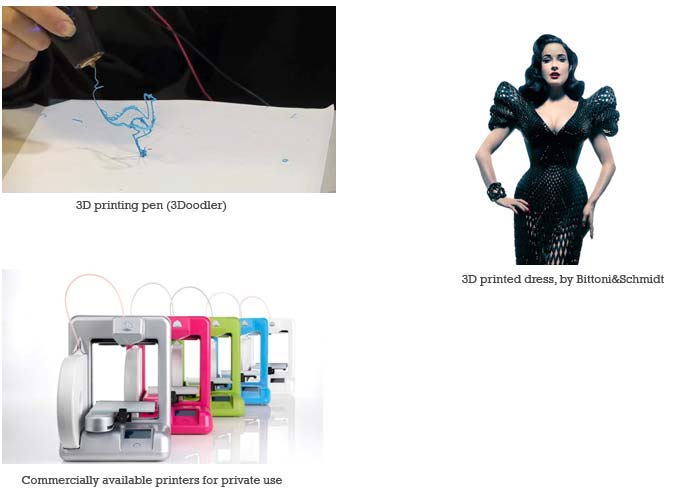
Fig. 8: Images Showing Implementation of 3D Printing
As of today, 3D printing has been applied in so many fields ranging from archeology to fashion. The purpose for which 3D printing was invented was for rapid prototyping, which is a crucial phase of product development and safety. Industrial applications include the feature of mass customization applied to goods since they do not require tool changing.Recently 3D printing is being applied in medicine to produce artificial body parts such as jaws, limbs and even artificial hearts. Even the clothing industry has been hit by recent advancement in material science. In archeology fossil reconstruction can be done with the combination of reverse engineering and 3D printing.
This remarkable feat achieved in the field of manufacturing has also seen recent advancements to make it available to common man. One of the latest innovations is the 3D printing pen with which you draw physical 3D objects in thin air, truly a remarkable device. 3D printing gives a medium for man to explore his creativity, to give shape to great ideas in his mind.

Fig. 9: 3D Printer Application
Filed Under: Articles


Questions related to this article?
👉Ask and discuss on Electro-Tech-Online.com and EDAboard.com forums.
Tell Us What You Think!!
You must be logged in to post a comment.