There is not one way, 3D printing can be carried out. Currently there are seven standard manufacturing processes recognized by the American Society for Testing and Materials (ASTM). All of these processes are additive in nature and differ only in the way layers are laid out. Efforts are on to innovate new processes other than the additive types but currently only additive manufacturing processes are applicable to 3D printing. Let’s see how Material Extrusion process implements 3D printing.
Material Extrusion
Extrusion is a term used for a process to create objects of fixed cross-sectional profile. In context to 3D printing, the term “Extrusion” has more specific meaning and refers to involvement of a “Hot End” and a “Cold End” in the process. Material extrusion is the most commonly used 3D printing process. Fused Deposition Modelling (FDM) is the most popular Material Extrusion Process apart from its open source equivalent Fused Filament Fabrication (FFF) which only differs in way being legally unconstrained.
Fused Deposition Modelling (FDM)
S. Scott Crump is the man behind development of the FDM technology. The technology was developed and patented in 1980’s. Later on, Crump started a company – Stratasys in 1988 which trademarked the term “Fused Deposition Modelling”.
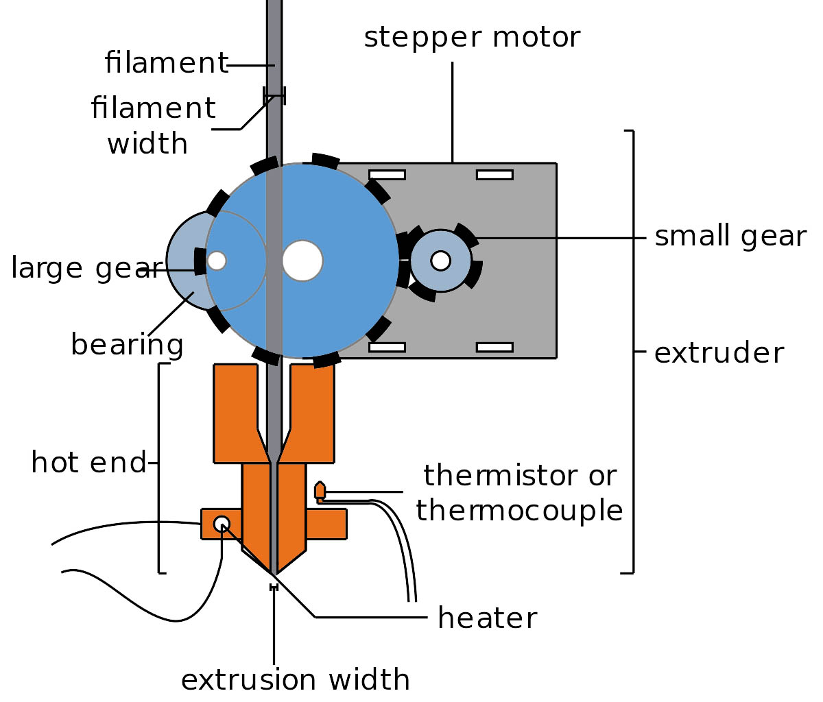
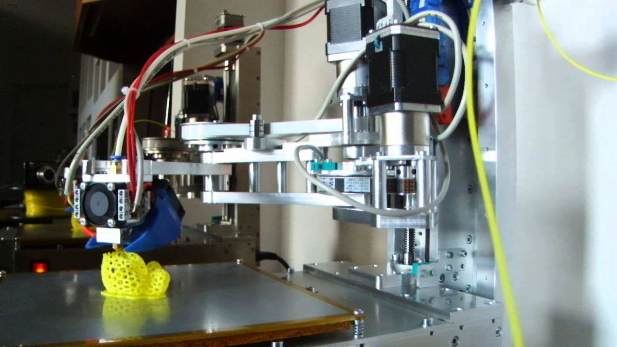
Being an extrusion process, FDM involves a hot end and a cold end. The hot end is an extrusion head to which the fabrication material is supplied by unwinding plastic filament or metal wire off a coil. The wire or filament is feed to the head’s nozzle in a worm-drive at a controlled rate. As the filament or wire enters the extrusion nozzle, it is heated past its glass transition temperature and gets melted.
When the molten filament or wire exits from the extrusion nozzle either exposed to air or an inert gas chamber, it solidifies immediately on a base or onto a preceding layer. The use of inert gas chambers is picking up high as it improves the adhesion of layers due to prevention from oxidation and improves the mechanical characteristics of the created object.
The extrusion nozzle is horizontally and/or vertically movable while the base platform can move along the remaining third plane. The vertical and/or horizontal movement of the nozzle is controlled by a numerical mechanism while its movement along the third plane is determined by a tool-path according to a computer aided manufacturing (CAM) software. The nozzle moves from bottom to up finishing deposition of each layer one after the other or remains stationary with respect to the moving platform. The motion of the nozzle is finally rectilinear in an XYZ plane guided by stepper motors. With recent innovations, deltabot has been successfully tried to move the nozzle end.
Usually in FDM, models are built using various types of thermoplastics and their support structures are generated simultaneously. The support structures are needed to keep the model in fixed orientation during the process. The materials used for creating support structures are respective soluble materials. There are two types of thermoplastics that are commonly used in FDM – Acrylonitrile Butadiene Styrene (ABS) and Polylactic acid (PLA). A number of other polymers like Polyamide (PA), lignin, Polycarbonate (PC), Polystyrene (PS), rubber etc. and some conductive materials are also used.
Fused Filament Fabrication (FFF)
Fused Filament Fabrication is a term coined by RepRap project which is an open source project for development of low-cost and affordable desktop 3D printers. This community driven project supplies Free and Open Source Hardware (FOSH) 3D printers. It is the result of successful attempts of RepRap project that the 3D printers which used to cost no less than $20,000 can now be assembled at affordable price of $1000 or less.
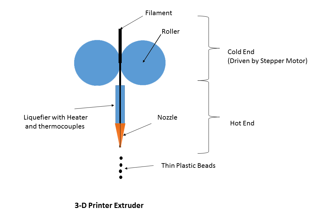
The process of Fused Filament Fabrication is almost similar to that of the Fused Deposition Modelling except that terms used to recognize various parts of the 3D printer and names for process specifications are different. The extrusion assembly where the feed is melted is referred as “Liquefier” and the layer paths deposited are called “Roads”. In most of the FFF printers the thermal environment of the chamber is specifically maintained to a temperature only slightly lower than that of the glass transition temperature of the material.
The FFF printers come with many options regarding the mechanical assembly of the extruder. Some of the common mechanical arrangement of extruder in FFF 3D printers are –
Cartesian-XY: The motion of Liquefier and the nozzle is bound to X-Y axis and the platform on which the model is built lowers down (Z-axis) as a layer successfully rasterize on the X-Y plane. The first 3D printer from RepRap – Darwin has the Cartesian-XY type.
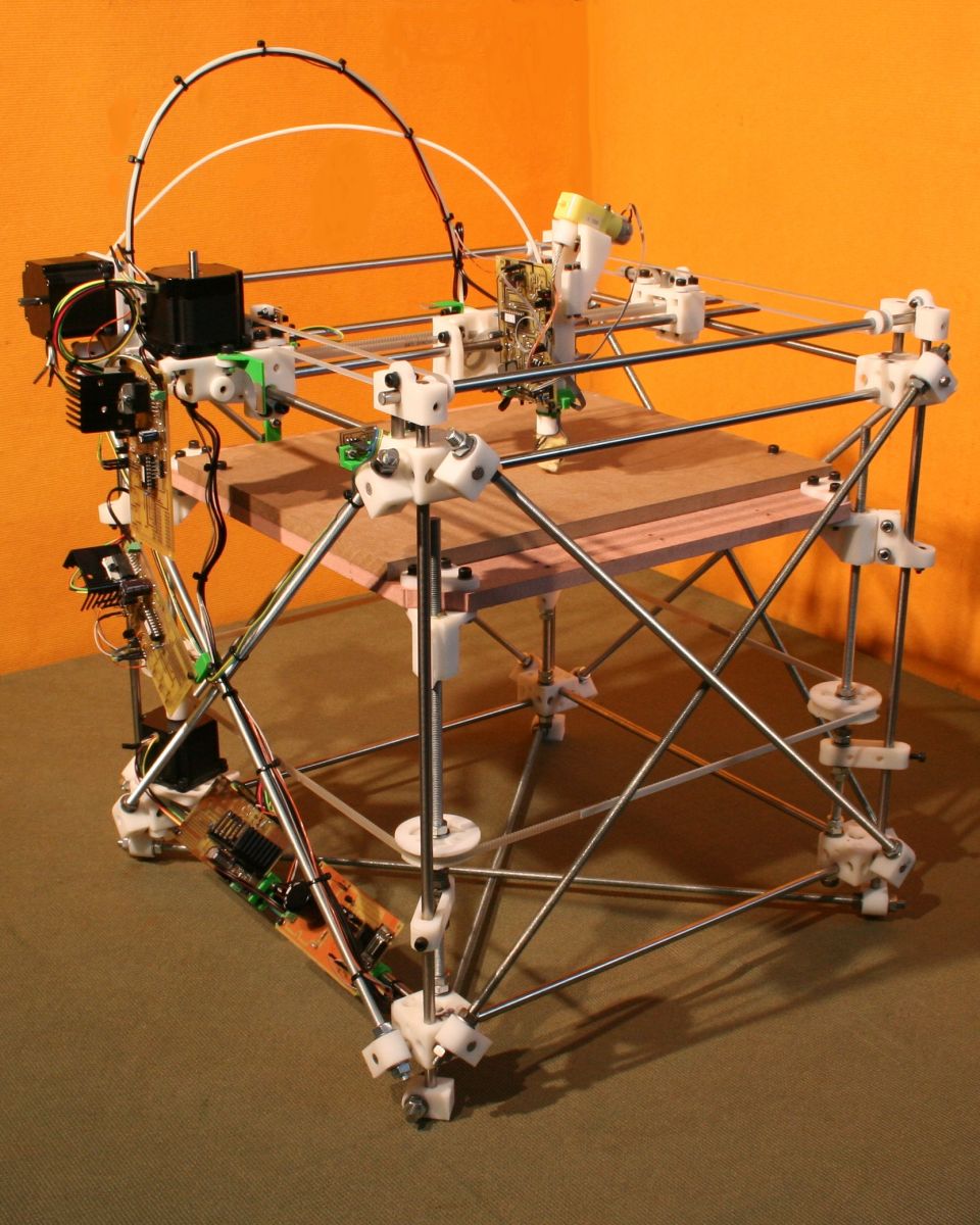
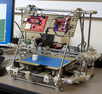
Cartesian-XZ: In this configuration, the extruder head moves in X and Z axis while the platform can move to and forth left and right along the Y axis. This way the platform can handle more load. The Mendel is the first Cartesian-XZ type 3D printer from RepRap project and it was built on Arduino. Other popular Cartesian-XZ FFF printers are RepRap Guru DIY Prusa I3 3D Printer and Original Prusa i3 3D.
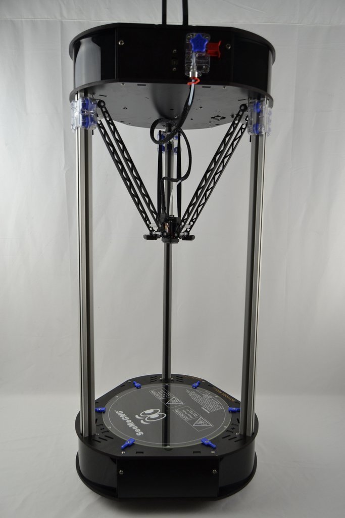
Delta: This is also a Cartesian configuration but the extruder head is held by three arms suspended in a triangular configuration. This type of arrangement allows greater accuracy and faster printing. Some affordable Delta 3D printers are Afinibot Micro Delta Kit, Folger Tech Kossel Auto Leveling Delta 3D Printer Kit, He 3D – Mega Delta 3D Printer Kit, Rostock MAX v3 etc.
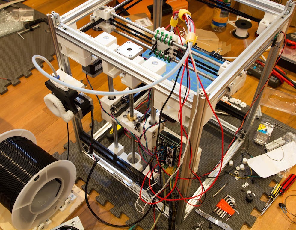
CoreXY: This Cartesian type extruder head arrangement is an improvement of tradition XY configuration. Instead of sequential movement in X-Y axis, CoreXY arrangement let the head move by a combined effect of x and y coordinates which are manipulated by a parallel system. Some examples of CoreXY 3D printers are RepRap-XY by “jand”, C-bot, AluXY by “Zelogik”, Vulcanus, AXIOM 20 Direct Drive, VSlot-CoreXY and Voron.
SCARA: SCARA is an abbreviation for Selective Compliant Assembly/ Articulated Robot Arm. The extruder head moves in a Cartesian style in all the axis (X, Y and Z)
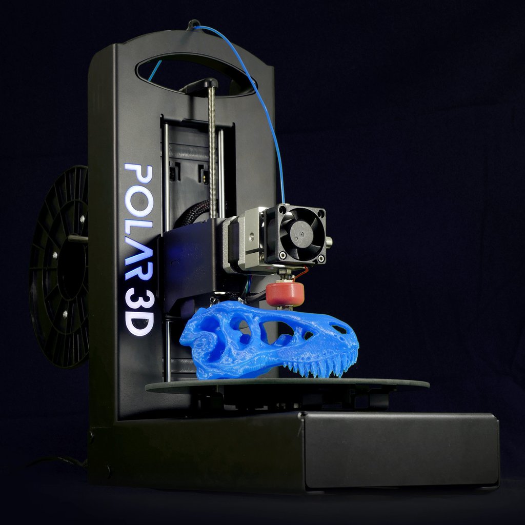
The Cartesian style FFF printers have three or four stepper motors to move the head in X, Y and Z axis while Polar printer has only two stepper motors mounted.
Vat Photopolymerisation is another standard 3D printing process recognized by ASTM. Learn more about Vat Photopolymerisation here.
You may also like:


Filed Under: Tutorials

Questions related to this article?
👉Ask and discuss on EDAboard.com and Electro-Tech-Online.com forums.
Tell Us What You Think!!
You must be logged in to post a comment.