Op-Amps require dual polarity supply for their proper operation. When working with battery supply, it is difficult to get dual power supply from battery supply as it requires more steps and components. So, presented here a simple circuit that provides +/- 5V from few components.
CIRCUIT AND WORKING
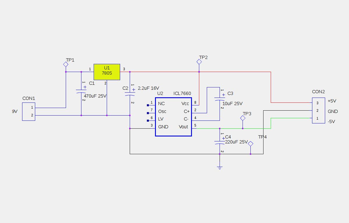
The circuit of +/- 5V supply from 9V battery is mentioned in the circuit diagram section.
It is built around monolithic CMOS voltage converter IC ICL7660A (U2) and linear voltage regulator IC LM7805 (U1). ICL7660A is configured as voltage inverter to convert the positive 5V supply to negative 5V supply. The linear voltage regulator converts the 9V battery input into regulated 5V. The regulated 5V output from IC 7805 is given to pin 8 of IC U2. The IC U2, capacitors C3 and C4 forms voltage inverter section that converts +5V to -5V. The converted dual polarity supply is available at connector CON2.
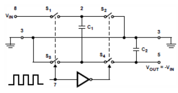
The working of ideal voltage converter can be understood by the figure shown below.

Fig. 1: Circuit Diagram of +/-5V supply from 9V Battery
During the first half cycle, switches S1 and S3 are closed (S2 and S4 are open during this cycle). The capacitor C1 is charged to +Vin volts.
During the second half cycle, switches S2 and S4 are closed (S1 and S3 are open during this cycle). The voltage on the capacitor C1 is shifted negatively to capacitor C2. The charge on the capacitor C1 is transferred to capacitor C2 assuming that the switches are ideal.
For proper working, verify the testpoints and their voltages.

Fig. 2: Table listing test points in circuit and measured voltage readings
NOTE :
The capacitor C2 should be placed nearby to IC2 to prevent device latch up. Do not give more than 10V for ICL7660, 12V for ICL7660A.
Circuit Diagrams
Filed Under: Electronic Projects


Questions related to this article?
👉Ask and discuss on Electro-Tech-Online.com and EDAboard.com forums.
Tell Us What You Think!!
You must be logged in to post a comment.