The main aim of this project is to understand that how Seven Segment Interfacing is done using Arduino. The project idea is to make an application based on Seven Segment Display. Here we demonstrate Seven Segment Interfacing and its application in a single project. Applications are Seven Segment Counter and Ultrasonic Sensor & Seven Segment based Distance Measurement project.
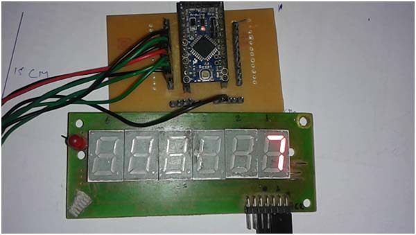
Fig. 1: Prototype of Arduino and Seven Segment Display based Distance Meter
Seven Segment Interfacing
It is not difficult to interface Seven Segment Display with Arduino. In the circuit of this pin a,b,c,d,e,f,g of Seven Segment Display is directly connected with Arduino pins 8,7,6,5,4,3,2.

Fig. 2: Block Diagram representing interfacing of Seven Segment Display with Arduino
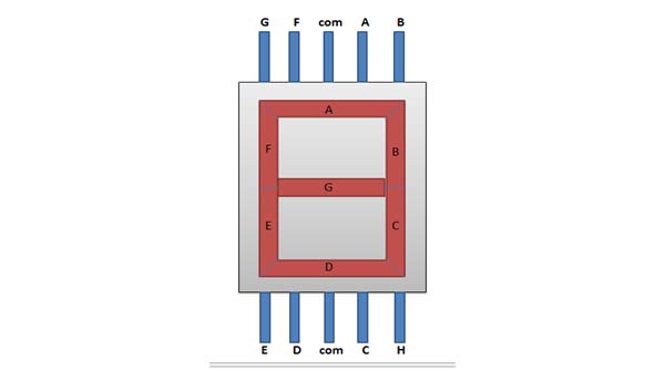
Fig. 3: Pin Diagram of Seven Segment Display
And then apply given process-

Fig. 4: Screenshot of Arduino Code used to display numbers on Seven Segment
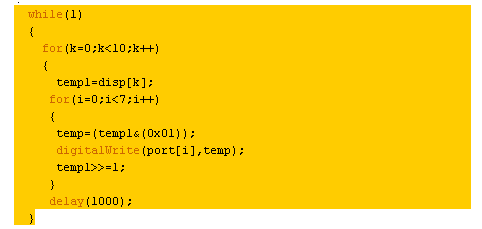
Fig. 5: Screenshot of Arduino Code used to display temperature on Seven Segment Display
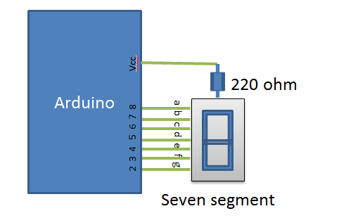
Fig. 6: Circuit Diagram of Seven Segment Display interfacing with Arduino Uno
Counter or Multiplexing of Seven Segments
Multiplexing of Seven Segments is nothing but a trick to drive more than one Seven Segment using a single port or common data line. By turning on and off the Seven Segment Display by controlling common pin of Seven Segments, we can drive many segments using single port or common data line.
Circuit Arrangement of multiplexing of segments is given below:
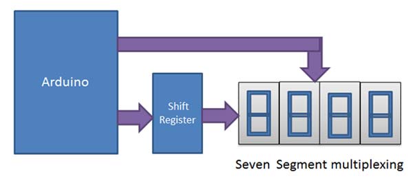
Fig. 7: Block Diagram representing multiplexing of Seven Segments
Here data pin of Seven Segment Display is connected to the shift register and Arduino shift in the data serially in shift register where shift register sends data to segments display. Data pin of all Seven Segments are connected together. This process is very fast.
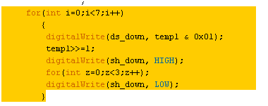
Fig. 8: Screenshot of Arduino Code used for multiplexing of Seven Segments
Circuit connections are given below
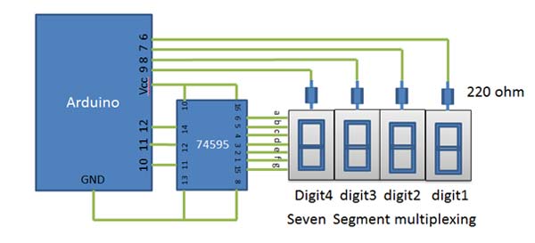
Fig. 9: Circuit Diagram of Seven Segment Multiplexing
Programming of this multiplexing is not difficult. In programming, delay plays a very important role for displaying proper number. If delay is not calibrated, number will not be displayed correctly.
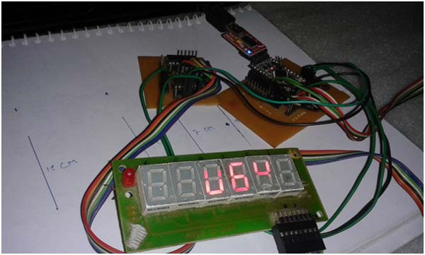
Fig. 10: Image showing numbers not displayed properly on Seven Segments because of insufficient delay
Here in this project I have used delay of five milliseconds after displaying every number for displaying proper numbers.
Delay(5);
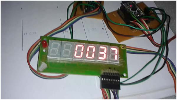
Fig. 11: Image showing numbers properly displayed on Seven Segments when delay of five milliseconds is provided
Distance Measurement using Ultrasonic Sensor
Distance Measurement
In this project Ultrasonic Sensor is used for measuring the distance.
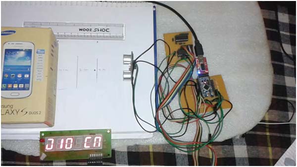
Fig. 12: Image of Arduino and Seven Segment Display based Distance Meter in action
Ultrasonic Sensor is a Transducer which consist Ultrasonic Transmitter and Receiver. Ultrasonic Transmitter sends Ultrasonic waves in environment and if these waves fall on any obstacle then it returns back to the receiver which detects these waves after some time interval and later by the method of calculations, we get an almost correct result (Distance).
In above figure “cn” is “cm” which means centimeters.
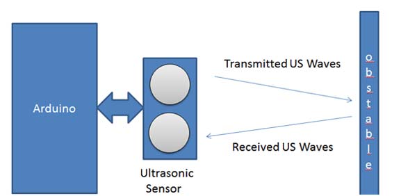
Fig. 13: Overview of working principle of ultrasonic sensor
Later the program converts this result to Single Digit Number for displaying on Seven Segment Display.
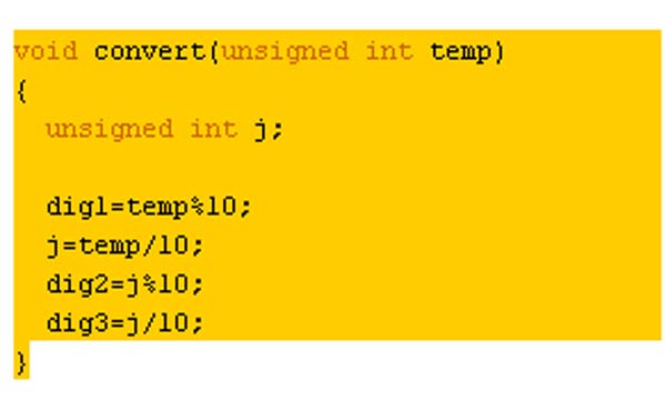
Fig. 14: Screenshot of Arduino Code used to break measured distance into digits
And now by using further process of multiplexing result will be displayed on Seven Segments.
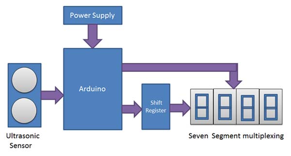
Fig. 15: Block Diagram of Arduino and Seven Segment Display based Distance Meter
Circuit connections are given below:
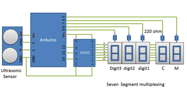
Fig. 16: Circuit Diagram of Arduino and Seven Segment Display based Distance Meter
This circuit gives output in centimeters.
Components Used
1. Arduino
2. Seven Segment Display
3. Ultrasonic Transceiver
4. Scale
5. Obstacle
6. Connecting Wire
7. Supply
Project Source Code
###


 #define trigger 2
#define echo 3
#define ds_down 12
#define sh_down 10
#define st_down 11
#define seg_one 9
#define seg_two 8
#define seg_thri 7
#define cm1 6
#define cm2 5


float time=0,distance=0;

unsigned int dig1, dig2, dig3;
char cm[2]={0x48, 0x46};
char disp[10]={0x40,0xF9,0x24,0x30,0x19,0x12,0x02,0xF8,0x00,0x10};
int i,temp,temp1,k;
void setup()
{
  Serial.begin(9600);
 pinMode(trigger,OUTPUT);
 pinMode(echo,INPUT);
  pinMode(ds_down, OUTPUT);
    pinMode(sh_down, OUTPUT);
    pinMode(st_down, OUTPUT);
    pinMode(seg_one, OUTPUT);
    pinMode(seg_two, OUTPUT);
    pinMode(seg_thri, OUTPUT);
   pinMode(cm1, OUTPUT);
    pinMode(cm2, OUTPUT);
}

void loop()
{
 digitalWrite(trigger,LOW);
 delayMicroseconds(2);
 digitalWrite(trigger,HIGH);
 delayMicroseconds(10);
 digitalWrite(trigger,LOW);
 delayMicroseconds(2);
 time=pulseIn(echo,HIGH);
 distance=time*340/20000;
 //Serial.println(distance);
 //distance=distance/10;
 convert(distance);
 displey();
}


void convert(unsigned int temp)
{
  unsigned int j;

dig1=temp%10;
  j=temp/10;
  dig2=j%10;
  dig3=j/10;
  //Serial.print(dig3);
 // Serial.print(dig2);
 // Serial.print(dig1);
 // delay(2000);
}

void displey()
{
  for(int i=0;i<100;i++)

 {
   for(int k=0;k<5;k++)
              {
                switch(k)
                {
                  case 0:
                  temp1=cm[0];
                  break;

                  case 1:
                  temp1=cm[1];
                  break;
                  case 2:
                  temp1=disp[dig1];
                  break;
                  case 3:
                  temp1=disp[dig2];
                  break;
                  case 4:
                  temp1=disp[dig3];
                  break;
                }
     for(int i=0;i<7;i++)
 {
        // temp=(temp1 & 0x01);
         digitalWrite(ds_down, temp1 & 0x01);
         temp1>>=1;
         digitalWrite(sh_down, HIGH);
         for(int z=0;z<3;z++);
         digitalWrite(sh_down, LOW);
        }

        digitalWrite(cm1, LOW);
          digitalWrite(cm2, LOW);
        digitalWrite(seg_one, LOW);
          digitalWrite(seg_two, LOW);
        digitalWrite(seg_thri, LOW);
        switch(k)
        {
         case 0:
        digitalWrite(cm1, HIGH);
        delayMicroseconds(10);
        break;

 case 1:
        digitalWrite(cm2, HIGH);
        delayMicroseconds(10);
        break;

case 2:
        digitalWrite(seg_thri, HIGH);
        delayMicroseconds(10);
        break;

case 3:
        digitalWrite(seg_two, HIGH);
        delayMicroseconds(10);
        break;

        case 4:
        digitalWrite(seg_one, HIGH);
        delayMicroseconds(10);
        break;
        }

        digitalWrite(st_down, HIGH);
        delayMicroseconds(10);
        digitalWrite(st_down, LOW);
        delayMicroseconds(5 000);

  }
}

}

###
Circuit Diagrams
| Circuit-Diagram-Arduino-Seven-Segment-Display-Based-Distance-Meter | 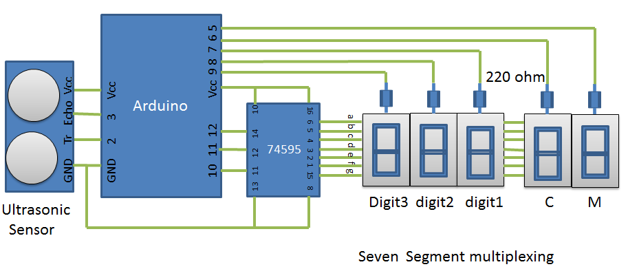 |
| Block-Diagram-Representing-Multiplexing-Seven-Segments |  |
Project Video
Filed Under: Electronic Projects
Filed Under: Electronic Projects


Questions related to this article?
👉Ask and discuss on EDAboard.com and Electro-Tech-Online.com forums.
Tell Us What You Think!!
You must be logged in to post a comment.