Project circuit diagram
- Nodemcu GPIO#0 is connected with Pin ‘a’ of 7 segment display.
- Nodemcu GPIO#1 is connected with Pin ‘b’ of 7 segment display.
- Nodemcu GPIO#2 is connected with Pin ‘c’ of 7 segment display.
- Nodemcu GPIO#3 is connected with Pin ‘d’ of 7 segment display.
- Nodemcu GPIO#4 is connected with Pin ‘e’ of 7 segment display.
- Nodemcu GPIO#5 is connected with Pin ‘f’ of 7 segment display.
- Nodemcu GPIO#16 is connected with Pin ‘g’ of 7 segment display.
7 segment display can work on 3.3 volts to +5 volts. Nodemcu WiFi module also works on 3.3 volts and outputs 3.3 volts at its power out pins. I used 3.3 volts out of nodemcu to power the common anode 7 segment display. Com/vcc pin of 7 segment display is connected 3.3 volt pin of nodemcu. Its better to connect a 110 ohm resistor in series to com/vcc pin of 7 segment display with 3.3 volt pin of nodemcu to limit the current. I did not used the register but i suggest to use it if your input supply to nodemcu esp8266 is low current output power source. Resistor will limit the current and prevents the nodemcu from low power reset. Circuit diagram of the project is given below.

const char* ssid = “Your SSID”;
const char* password = “Your Wifi Password”;
In the loop function nodemcu(server) is checking for a client request as soon as the client request arrives nodemcu starts decoding the request. Performs the functions requested in the HTTP request by client. Before closing the client HTTP request server-nodemcu replies back to client with the updated status of 7 segment display.
|
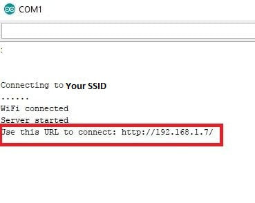
Just build the circuit and download the above code in your nodemcu esp8266 WiFi module. After successfully downloading the code in your nodemcu. Open the arduino serial monitor from the arduino ide. You will see in arduino serial monitor nodemcu starting up, requesting IP from router and after IP assignment starting its server. Server address will be printed in the arduino serial monitor. This server address is actually the web page address on which our 7 segment display controls are present. One must has to enter this URL/Address in his browser to access the seven segment control web page.
|
|
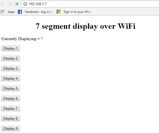
As soon as you hit the 7 segment display web page control address/IP in your browser a web page will appear in browser. Web page will look like some thing below. Main project heading is on the top. Then the current displayed number on seven segment status is shown. Below status are control buttons. Pressing any button will automatically display the corresponding number on 7 segment.
- if (request.indexOf(“/Req=1”) != -1)
becomes true. Now what ever is in this statement, nodemcu esp8266 will execute it. In this statement I am printing 1 on seven segment display. To print we know we have to make the seven segment pins off and on. So for 1 we have to switch on ‘e’ and ‘f’ pins of seven segment and all other will be off. The code below is executed in the above statement and in it ‘e’ and ‘f’ are switched on.
digitalWrite(a, HIGH);
digitalWrite(b, HIGH);
digitalWrite(c, HIGH);
digitalWrite(d, HIGH); //Displaying 1
digitalWrite(e, LOW);
digitalWrite(f, LOW);
digitalWrite(g, HIGH);
Note: We are using common anode 7 segment display. So to glow an led corresponding to seven segment pin we have to make it low. This is done in the above statements.
Future Work
This tutorial is just to teach you how to interface and control a 7 segment display over WiFi through nodemcu WiFi module. Further you can set time of a digital watch with the same protocol. Display characters on lcd. Make a diy web key pad etc.
Filed Under: ESP8266., Microcontroller Projects

Questions related to this article?
👉Ask and discuss on Electro-Tech-Online.com and EDAboard.com forums.
Tell Us What You Think!!
You must be logged in to post a comment.