● 8 player quiz buzzer can be used in various competition organise in school and colleges to identify the team who has pressed the buzzer first.
● Advantage of this quiz buzzer circuit is once a team has press the switch others are not allowed to press the switch therefore it block other participant.
● So with the help of this circuit you can easily identify the contestant who has press the switch first.
● You can use variable power supply ranging from 6V to 15V.
● You can provide power supply with the help of adapter readily available in market or you can make your own power supply with help of transformer and bridge rectifier.
[[wysiwyg_imageupload:10870:]]
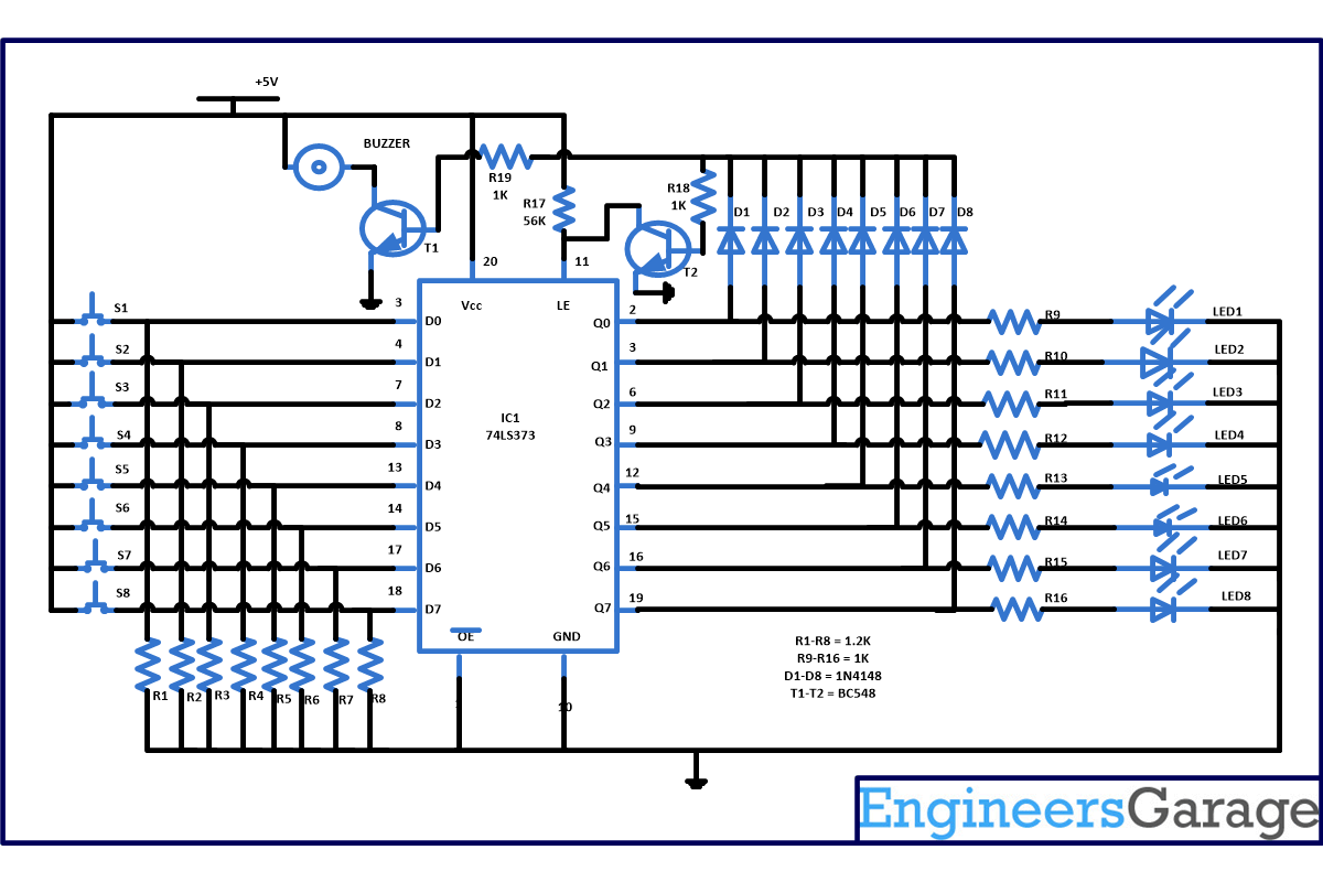
This simple 8 player quiz buzzer circuit is based on one IC namely 74LS373 with few more easily available components. 74LS373 is a 3 state octal D type transparent latch and edge triggered flip flop. When its enable pin 11 is high the output will follow the data feed on its input. And when enable pin is low the output will be latched at the level of the data means no further change is allowed in output. 74LS373 contain 8 D type flip flop in a single chip. It also has the facility to buffer control inputs. In short 74LS373 transfer signals from D0 to D7 at the input pin to the corresponding outputs Q0 to Q7.
Working of circuit
As you can see in the circuit diagram we have made the inputs pin D0 to D7 initially low with the help of resistor R1 to R8 respectively. As you can see from the circuit diagram one terminal of switches are connected to power supply and remaining terminal of switches are connected to input pin D0 to D7.
When power supply is provided to circuit initially all data inputs are low. And when any contestant presses the switch, let say contestant first pressed the switch S1 than data input line goes high and enable the latch and output pin 2 that is Q0 will become high and the LED1 start glowing and this high will also trigger the transistor T1 connected with the help of diode D1 and buzzer also start sounding.
Now this high is also provided to base of transistor T2 and its collector is also high so transistor will not conduct means it will ground the pin 11. And when pin 11 that is latch enable pin is grounded it will hold the present state until you reset the power supply. Therefore other participant switch are blocked. Means if they press the switch than also their input pin does not go high. This indicate that participant 1 has press the switch first.
For easy identification of contestant put the participant name or number in front of the LED. And provide a power reset switch to host so that after every question when buzzer is pressed and team who has pressed the switch is identify host can reset the circuit for next round.
Circuit Diagrams
Project Components
Project Video
Filed Under: Electronic Projects
Filed Under: Electronic Projects


Questions related to this article?
👉Ask and discuss on EDAboard.com and Electro-Tech-Online.com forums.
Tell Us What You Think!!
You must be logged in to post a comment.