Engineers Garage

  • Projects and Tutorials
    • Circuit Design
    • Electronic Projects
      • 8051
      • Arduino
      • ARM
      • AVR
      • PIC
      • Raspberry pi
      • STM32
    • Tutorials
    • Components
  • Articles
    • EG Blogs
    • Insight
    • Invention Stories
    • How to
    • What Is
    • News
      • EE Design News
      • DIY Reviews
      • Guest Post
      • Sponsored Content
  • Forums
    • EDABoard.com
    • Electro-Tech-Online
    • EG Forum Archive
  • Digi-Key Store
    • Cables, Wires
    • Connectors, Interconnect
    • Discrete
    • Electromechanical
    • Embedded Computers
    • Enclosures, Hardware, Office
    • Integrated Circuits (ICs)
    • Isolators
    • LED/Optoelectronics
    • Passive
    • Power, Circuit Protection
    • Programmers
    • RF, Wireless
    • Semiconductors
    • Sensors, Transducers
    • Test Products
    • Tools
  • EE Resources
    • DesignFast
    • LEAP Awards
    • Oscilloscope Product Finder
    • Video
    • White Papers
    • Webinars
  • EE Learning Center
  • Women in Engineering

Seven segment display interfacing with 8051(89c51,89c52) Microcontroller

April 15, 2019 By EG Projects

This is a simple tutorial on how to interface seven segment display with 8051(89c51,89c52) microcontroller. The post/tutorial explains the connections and interfacing of 7 segment display with 89c51 microcontroller. 7 segment display is interfacedwith Port-1 of 89c51 microcontroller. Numeric characters from 1 to 9 and alphabets from A to F will be displayed on single seven segment display using 89c51 microcontroller.

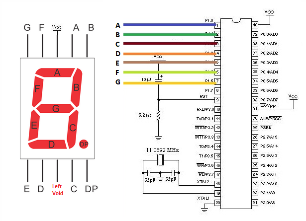
Types of 7 segment display

​There are basically two types of seven segment displays Anode and Cathode. First i would like you to take a simple tutorial on whats the difference between the two

  • Difference between common anode and cathode seven segment displays.

Above Tutorial will help you in determining which seven segment you are using anode or cathode. You will be familiarize with the pin out and internal structure of the seven segment display. The upper tutorial will also explain you what are the pros and cons of using anode and cathode seven segment displays.

7 segment display with 8051 microcontroller – circuit diagram

The circuit of the project is straight forward. No messy circuit connections. I am using common anode seven segment display in the project.  Common anode 7 segment display led’s are switched ON when we make any led pin ground. 11.0592 Mhz crystal is used to provide clock to 89c51 microcontroller. Circuit diagram of 7 segment interfacing 8051 microcontroller is given below.
7 segment display with 8051 microcontroller

7 segment display with 8051 microcontroller

The above 7 segment display interfaced with 89c51 micrococntroller translates to some thing given below. I just removed the wires in the above diagram. Wires makes circuit messy. Both the circuits are same. No difference in connections or working.  
circuit diagram

seven segment display interfacing 8051(89c51) microcontroller-circuit diagram

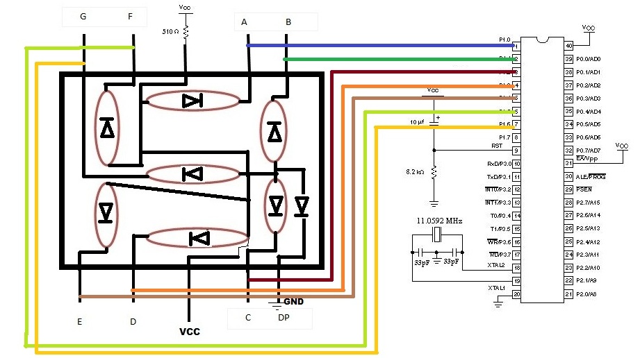
8051 microcontroller port-1 interfaced with 7 segment – Individual pin connections

7 segment pins connection’s with 89c51 microcontroller port-1 individual pins is shown in the below picture. 7 segment display only has 7 sevens pins and 8051 microcontroller port-1 is 8-bit wide. So one pin of 89c51 port-1 is left void.
8051 Port 1 pin assignment

8051(89c51,89c52) Port 1 pin assignment to seven segment display

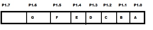
How numbers and characters are displayed on 7 segment display?

89c51 microcontroller port pins are assigned to seven segment in the above order(picture). Instructions like P1=0xCF are hexadecimal instructions and they are making port 1 pins high or low.

Like P1=0xCF is equivalent to 11001111(C=1100 and F=1111) in binary. This instruction makes f & e(P1.5 and P1.4) pins of seven segment ground and the corresponding led’s to these pins becomes high. which prints 1 on the seven segment display. 

Below are the full instructions used to display numbers and alphabets on the 7 segment display. These instructions are hard coded in the code.

  • Making 1- f e                      is grounded P1=0xCF;   11001111
  • Making 2- a b g e d            is grounded P1=0xA4;   10100100
  • Making 3- a b c d g            is grounded P1=0xB0;   10110000
  • Making 4- b c f g                is grounded P1=0x99;   10011001
  • Making 5- a c d f g             is grounded P1=0x92;   10010010
  • Making 6- a c d e f g          is grounded P1=0x82;   10000010
  • Making 7- a b c                  is grounded P1=0xF8;   11111000
  • Making 8- a b c d e f g       is grounded P1=0x00;   00000000
  • Making 9- a b c f g             is grounded P1=0x98;   10011000
  • Making A- a b c e f g          is grounded P1=0x88;   10001000
  • Making B- a b c d e f g       is grounded P1=0x00;   00000000
  • Making C- a d e f                is grounded P1=0xC6;  11000110
  • Making D- a b c d e f          is grounded P1=0xC0;  11000000
  • Making E- a d e f g             is grounded P1=0x86;   10000110
  • Making F- a e f g                is grounded P1=0x8E;   10001110​

7 segment with 89c51 microcontroller – Code

Coming to the code first i included the necessary header file reg51.h. If you are using keil for writing and compiling code you have to include this library other wise their will be an error during compilation of the code. If you are using 89c52 or 89s52 include library reg52.h instead of reg51.h. Then a delay function is used to give some delay to a particular character/alphabet  or number to remain printed on the seven segment display. Delay is for viewing the character/alphabet or number for some time and then moving to next. If their is no delay the numbers will display so fast that we can not see them. In main function my first instruction is P1=0x00. This instruction is initializing Port-1 as output port. Rest of the instructions are in hexa-decimal form and there functions are discussed above.

Note: If you are using Common cathode seven segment display the upper commands will be same just make a little change turn 0(zeros) to 1(ones) and 1(ones) to 0(zeros) because common cathode lit its leds when any pin is high.

​The while 1 loop is continuously running our seven segment display. Means continuously printing characters and numbers on it. 

More microcontroller projects involving 7 segment display. Each microcontroller project contains free source code and circuit diagram of the project. Seven segment display is used for different purposes in each project. 7 segment microcontroller project list is below. 

7 segment display interfaced with arduino uno

7 segment display interfaced with stm32 microcontroller

7 segment display controlled over WiFi using Nodemcu

Download the project files. Folder contains Code(c++,hex). Give mus your feed back on the post. If you have any questions just leave them below in the comments section .
8051-seven segment project 

Related Articles Read More >

A Bluetooth-controlled datalogger robot
touch bell push
How to design a touchless bell push using Arduino
SMS-enabled scrolling message board using Arduino
Interfacing stepper motor with 8051(89c51,89c52 ) microcontroller

Featured Tutorials

  • Screenshot of Raspbian OS on Raspberry Pi RPi Python Programming 03: Raspberry Pi as Linux System
  • Raspberry Pi Models RPI Python Programming 02: Raspberry Pi Models
  • Raspberry Pi 4 RPi Python Programming 01: Introduction to Raspberry Pi 4
  • RPi Python Programming 05: Introduction to Python
  • RPi Python programming 04 RPi Python programming 04: Setting up Raspberry Pi Linux computer
  • Python Basics RPi Python Programming 06: Python basics

Stay Up To Date

Newsletter Signup

EE Training Center Classrooms

“ee

“ee

“ee

“ee

Recent Articles

  • Arduino’s L293D motor driver shield guide
  • NXP launches its first Wi-Fi 6E Tri-Band system-on-chip
  • Nexperia launches industry’s first 80 V RETs for high-voltage bus circuits
  • TDK releases low-profile medical sensors
  • Getting started with Raspberry Pi
...

RSS EDABOARD.com Discussions

  • What the best way to store data of size ( 90,000 * 32) bit (taken from a text file) using VHDL?
  • HSPICE Simulation refuses to match the Spectre Simulation
  • How to draw a helical coil around a rectangular core in Maxwell?
  • Where can I find the description of each layer in TSMC's pdk?
  • Same geometry but slightly different results

RSS Electro-Tech-Online.com Discussions

  • Where has the fun gone?
  • Where can I find a pole pig?
  • Voltage based relay
  • XC8 v2.31 Help: Integer Arithmetic With Numbers Larger Than 32 Bits?
  • new to Ardunio but trying to compile
Engineers Garage
  • Analog IC TIps
  • Connector Tips
  • DesignFast
  • EDABoard Forums
  • EE World Online
  • Electro-Tech-Online Forums
  • Microcontroller Tips
  • Power Electronic Tips
  • Sensor Tips
  • Test and Measurement Tips
  • 5G Technology World
  • About Us
  • Contact Us
  • Advertise

Copyright © 2021 WTWH Media LLC. All Rights Reserved. The material on this site may not be reproduced, distributed, transmitted, cached or otherwise used, except with the prior written permission of WTWH Media
Privacy Policy | Advertising | About Us

Search Engineers Garage

  • Projects and Tutorials
    • Circuit Design
    • Electronic Projects
      • 8051
      • Arduino
      • ARM
      • AVR
      • PIC
      • Raspberry pi
      • STM32
    • Tutorials
    • Components
  • Articles
    • EG Blogs
    • Insight
    • Invention Stories
    • How to
    • What Is
    • News
      • EE Design News
      • DIY Reviews
      • Guest Post
      • Sponsored Content
  • Forums
    • EDABoard.com
    • Electro-Tech-Online
    • EG Forum Archive
  • Digi-Key Store
    • Cables, Wires
    • Connectors, Interconnect
    • Discrete
    • Electromechanical
    • Embedded Computers
    • Enclosures, Hardware, Office
    • Integrated Circuits (ICs)
    • Isolators
    • LED/Optoelectronics
    • Passive
    • Power, Circuit Protection
    • Programmers
    • RF, Wireless
    • Semiconductors
    • Sensors, Transducers
    • Test Products
    • Tools
  • EE Resources
    • DesignFast
    • LEAP Awards
    • Oscilloscope Product Finder
    • Video
    • White Papers
    • Webinars
  • EE Learning Center
  • Women in Engineering