This is the same mechanical structure used in previous project but now it is interfaced with micro-controller 89C51. All the motions of robot will be controlled by 89C51. Full 360 degree rotation in horizontal plane and 90 degree movement in vertical plane is achieved.
Once all the parameters are set operation is fully automatic. Means set the angle of rotation and angle of inclination to pick up an object and object will be automatically picked up. Now again repeat the procedure to place an object somewhere else.
The project is divided in to two parts (1) Mechanical Part (2) Electronic Part
click here to see complete mechanical structure figure, explanation etc. let’s directly move to electronic part
Electronic Part:-
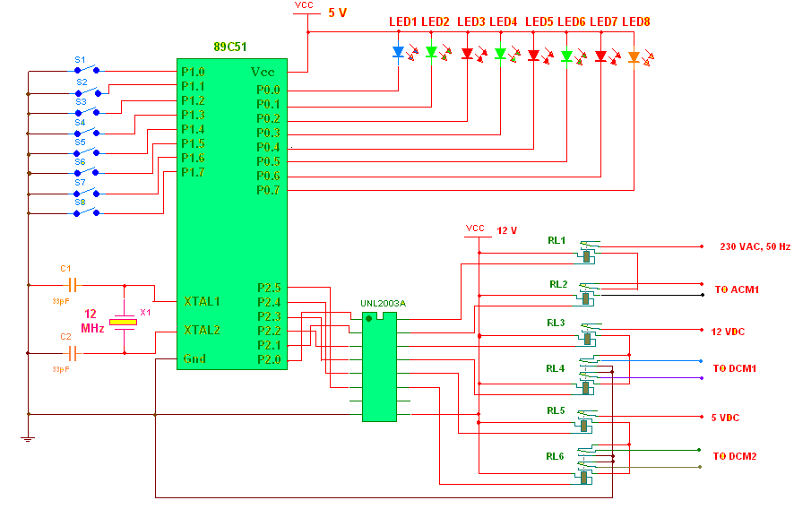
Shown in Circuit Diagram tab 1.
There are two main components in circuit micro controller 89C51 and current driver chip UNL2003A. 89C51 is the heart of circuit which perform all the required tasks like
· Accepts input from user through keypad (S1-S8)
· Generates indication on LED panel (LED1 – LED8) of every action being performed
· Generates suitable signals to energize / deenergize all relays (RL1-RL6) to run different motors
Connections:- out of four ports of 89C51 I have utilized three ports one for input and two for output. Port P1 is used as input port. All port pins are connected to ground through push button switches S1 to S8. P0 port is configured as output port and all pins are connected to cathodes of LEDs LED1 – LED8. Anode of each LED is shorted and connected to 5 V Vcc. Pins of Port P2 are directly connected to inputs of current driver chip UNL2003A. Outputs of this chip drives six different relays RL1 – RL6.
Operation
Operation:- as written above the controller takes care of all the required tasks. The program written in it will do the required job. First thing is to detect key press and then perform required tasks. 8 different keys are used here for 8 different tasks. Please refer the table
|
Switch |
Function |
|
SW1 |
Start rotating ACM1 clockwise / anticlockwise for specified angle |
|
SW2 |
Selects the direction of rotation of ACM1 |
|
SW3 |
Increase the rotating angle of ACM1 |
|
SW4 |
Decrease the rotating angle of ACM1 |
|
SW5 |
Move the hand up word / down word |
|
SW6 |
Selects direction of moving for DCM1 |
|
SW7 |
Open sliding grip |
|
SW8 |
Close sliding grip |
When controller detects any key press event it will directly switch to that particular subroutine. 8 different subroutines are written for 8 different functions given above. To start or stop any AC / DC motor 89C51 will just will just switch ON / OFF that particular relay by giving high / low logic on port P2 pins.
Different LEDs are used to indicate different actions being performed. Please refer the table.
|
LEDs |
Indication |
|
LED1 |
Key press event |
|
LED2 |
Clockwise direction for ACM1 |
|
LED3 |
Anticlockwise direction for ACM1 |
|
LED4 |
Hand will move up |
|
LED5 |
Hand will move down |
|
LED6 |
Blinks when ever angle of ACM1 is increased. Stays ON if maximum limit of angle (180 deg) is reached. |
|
LED7 |
Blinks when ever angle of ACM1 is decreased. Stays ON if minimum limit of angle (30 deg) is reached. |
|
LED8 |
Indicates running of each motor |
First, when one will press SW1 will switch ON RL1 for 2.5 sec so ACM1 will rotate for 2.5 sec means 30 degree rotations.
By pressing SW2, it will alternatively switch ON or OFF RL2 to change the direction of ACM1. Means by pressing it ones it will set anticlockwise direction and again when you press relay will be OFF and direction will be again set to clockwise.
Pressing SW3 will increase the delay for which ACM1 will rotate and thus it will increase angle of rotation. Delay is increased in multiple of 2.5 means 2.5, 5 ,7.5, 10………..As angle approaches to 180 deg means 15 sec delay no more increase in angle.
Pressing SW3 will decrease the delay for which ACM1 will rotate and thus it will decrease angle of rotation. Delay is decreased in multiple of 2.5 means 10, 7.5, 5, 2.5………..As angle approaches to 30 deg means 2.5 sec delay no more decrease in angle
RL3 will be switched ON till you press and hold SW5. Thus DCM1 will rotate till SW5 is pressed and hand will move up or down
By pressing SW6, it will alternatively switch ON or OFF RL4 to change the direction of DCM1. Means by pressing it ones it will set upward direction for hand and again when you press relay will be OFF and direction will be again set to downward.
Pressing and holding SW7 will switch ON RL5 and will run DCM2 thus opening the grip. Same way by pressing and holding SW8 will switch RL5 & RL6 both and this will run DCM2 in reverse direction thus closing the grip
Circuit Diagrams
Filed Under: Electronic Projects

Questions related to this article?
👉Ask and discuss on EDAboard.com and Electro-Tech-Online.com forums.
Tell Us What You Think!!
You must be logged in to post a comment.