here are different techniques to control speed of AC motor. One of the very popular of them is by applying chopped AC waveform – means changing phase angle of applied AC waveform. This method is used in many different devices like
The firing angle of a thyristor like TRIAC - that gives supply to motor, is delayed to decrease the motor speed or it is fired earlier to increase motor speed. As firing angle is changed, the part of AC waveform applied to motor is chopped more or less. So the average AC voltage applied to motor changes – that changes speed of motor.
There are different techniques to control speed of AC motor. One of the very popular of them is by applying chopped AC waveform – means changing phase angle of applied AC waveform. This method is used in many different devices like
1. In domestic fan regulator to vary speed of fan
2. In electric drill machine to rotate shaft at different speed
3. In modern electric hand blander machines
4. To vary the speed of blowers or fans used in industries for different application
The firing angle of a thyristor like TRIAC – that gives supply to motor, is delayed to decrease the motor speed or it is fired earlier to increase motor speed. As firing angle is changed, the part of AC waveform applied to motor is chopped more or less. So the average AC voltage applied to motor changes – that changes speed of motor.
Here the given circuit uses same principle to vary AC motor speed. It uses IC555 to generate variable width pulse that varies firing angle of TRIAC through DIAC. It first takes zero reference of AC waveform from Zero cross detector circuit (ZCD) and chops the AC input applied to motor by increasing/decreasing phase angle of TRIAC using variable pulse width output of IC555.
Let us first understand the block diagram of the circuit. It is followed by circuit description and its detailed working and operation
Block diagram description:
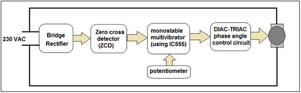
Fig. 1: Block Diagram of 555 IC and ZVC based AC Motor Speed Controller
Let us understand functions of different blocks to understand how the circuit works
Bridge rectifier – it generates rectified output from applied AC input
ZCD – it generates short duration positive and negative pulses when AC waveform crosses zero mark. It is used as reference to chop AC waveform applied to motor
Monostable multivibrator – it generates pulses whose width can be varied (PWM) using potentiometer and it changes firing angle of TRIAC through DIAC
DIAC-TRIAC phase angle control circuit – it applies chopped AC waveform to motor and varies speed of AC motor
So the circuit varies speed of AC motor by changing firing angle of TRIAC by applying PWM generated using IC555 connected in monostable mode. As the width of IC555 output pulse is varied using potentiometer, the firing angle of TRIAC changes and motor speed changes
Circuit Description:
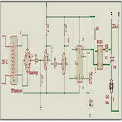
· 230V @ 50 Hz AC is applied at the primary of transformer T1 (0-12, 500 mA). It’s secondary is connected with AC input terminals of bridge rectifier BR1
· Rectified output is given to base of transistor Q1 through voltage divider formed by resistors R2 (1K) & R2 (1K)
· Collector output of Q1 is fed to base of transistor Q2 through R1 (470Ω). Q1 and Q2 both are connected in switch configuration as shown
(Check the circuit diagram tab for complete circuit for AC Motor speed control)
· The output of Q2 is applied at the trigger input of first NE555 chip U1. It is configured in monostable mode. Timing components RV1 (10K pot) and C1 (1 µF) decides width of output pulse
· Output of U3 is applied to cathode input (pin no. 2) of internal LED of opto-coupler MOC3021
· Anode input (pin no.1) of internal LED of MOC3021 is connected to Vcc through current limiting register R11 (220Ω).
· Between pin 6 and pin 4 of MOC3021 there is a DIAC. Pin no 6 is connected to MT2 terminal of TRIAC BT136 through 470 Ω resistor and pin no. 4 is connected to gate of TRIAC.
· AC Motor is connected between terminal MT1 of TRIAC and neutral wire of AC line as shown. The phase wire of AC line is applied to MT2 terminal of TRIAC
Circuit operation:
Let us understand circuit operation block by block with help of waveforms at different points A, B, C, D, E and F indicated in the circuit diagram.
Bridge rectifier – it is made up of transformer and Diode Bridge. The transformer step down 230 VAC to 12 VAC. The 1st waveform in figure shows this waveform at point ‘A’. This AC wave is applied to Diode Bridge that simply generates full wave rectified output. It is shown as 2nd waveform in figure at point ‘B’.
Zero cross detector (ZCD) – this section consists of just two transistors Q1 and Q2 that are connected in switch configuration. The rectified output of bridge rectifier is given to base input of Q1.
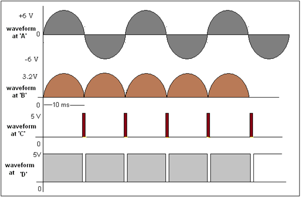
Fig. 2: Timing Diagram showing Zero Crossing Detection
Because transistor it is connected in switch configuration, when the input at the base becomes lower than 0.7 V it comes into cut off and produces very short duration positive pulse at point ‘C’. That is shown as 3rd waveform in figure. As this positive pulses are fed to Q2 which is again connected in switch configuration, it will produce negative pulse at point ‘D’ of same width of positive pulse. This is shown as 4th waveform
Monostable multivibrator – When it gets –Ve pulse from ZCD section on its trigger input it will generate positive output pulse whose width is varied. The time period of this pulse is determined by value of pot RV1 and capacitor C1. The values of RV1 and C1 are chosen such that the circuit generates pulse from 0 – 10 ms width as pot is varied.
DIAC-TRIAC phase angle control: – the output of IC555 is given to optocoupler chip MOC3021. Because Anode of internal LED is connected to Vcc, when low output of IC555 is applied to cathode, current passes through LED and it triggers internal DIAC. So till the IC555 output is high, the DIAC does not conduct and it does not trigger TRIAC. As IC555 output time period over – the output again goes low – the DIAC conducts – it triggers TRIAC. As the width of IC555 output is varied the TRIAC triggers earlier of later. This is explained better with the help of waveforms given in following figure
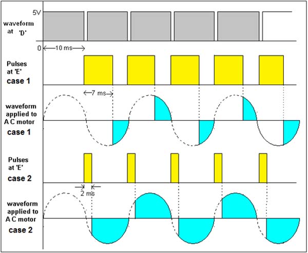
Fig. 3: Timing Diagram showing Phase Angle Control
Let us consider two cases.
Case 1:
- In this first case pulse width is 7 ms, so the LED remains off for 7 ms and turns on for rest 3 ms
- So DIAC will also conduct for only 3 ms and it will trigger TRIAC for 3ms
- The part of AC waveform applied to AC motor is shown as 3rd waveform. The motor is less because less AC voltage is applied
Case 2:
- For this case the pulse width is decreased from 7ms to 2 ms
- LED remains OFF for 2 ms and it is ON for rest of 8 ms
- The DIAC conducts for 8 ms time and TRIAC will also conducts for 8 ms time
The 5th waveform shows the part of AC waveform applied to AC motor. The motor speed will increase because more voltage is applied
Thus as firing angle (phase angle) of TRIAC is changed by PWM wave the motor speed changes.
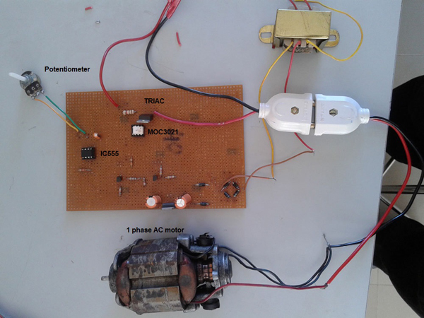
Fig. 4: Prototype of 555 IC and ZVC based AC Motor Speed Controller
Circuit Diagrams
Project Video
Filed Under: Electronic Projects
Filed Under: Electronic Projects

Questions related to this article?
👉Ask and discuss on EDAboard.com and Electro-Tech-Online.com forums.
Tell Us What You Think!!
You must be logged in to post a comment.