It is easy to switch DC devices and even control operations of DC devices using Pulse Width Modulation. When it comes to controlling the AC devices, the switching of the AC devices is also not complicated and can be easily done with the help of relays. For controlling operations of an AC device, the voltage supplied to it needs to be controlled. The AC voltage supply to a load can be controlled by a technique called Zero Voltage Crossing Detection and Fire Angle control.
In this project, an AC device, a 15 Watt bulb taken for demonstration purpose is controlled using the same technique. This project is an IOT (Internet of Things) project built on an IOT board – Photon from the company Particle. So the AC voltage control is carried out over the internet. A webpage allows the user to increase or decrease supply voltage and the project device connected to Particle’s Cloud Server receives the control commands over the internet and executes voltage control operation accordingly.
Controlling AC devices operationally is a bit tricky. An alternating voltage changes its sign periodically. The alternating voltage supplied to households is usually the sine wave. An alternating voltage can be another form of the wave also. Irrespective of the waveform, an alternating voltage in the first half of every cycle flows in one direction reaching to a peak voltage and then drops down to zero level. Then in the next half of each cycle, it flows in alternate direction reaching to a peak voltage and then drops down to zero level.
The rise and drop of voltage in alternate direction is graphically shown with a negative sign of voltage and voltage curve. The cycles are repeated throughout the voltage supply. For controlling AC appliances operationally, the peak voltage of both the halves of a cycle needs to be chopped off. For this, it is important to detect when voltage alternates its direction. The point on voltage curve where it alternates direction is called zero voltage crossing.
The zero voltage crossing of AC voltage can be detected by first rectifying it using full wave rectifier and then using an optoisolator which will switch OFF and ON upon zero voltage crossings and past zero voltage crossings respectively. The output of optoisolator can then be passed to the microcontroller to indicate zero voltage crossings to it.
For controlling AC voltage to a load, TRIAC needs to be used. TRIAC (Triode for AC) is commonly used for power control and switching applications. The TRIAC can be feed control using an optocoupler which itself would be driven by a microcontroller pin.
The project is built upon Particle Photon and 4N25 optoisolator with a full bridge rectifier is used for zero voltage crossing detection. The 3021 optocoupler and BT136 TRIAC are used for chopping off AC voltage to the load. The tasks of zero voltage crossing detection and switching of 3021 IC are programmatically controlled by the Photon. The Photon is an Arduino Compatible IOT board developed and supplied by the Particle (Former Spark). The program code on Photon needs to be written on Web IDE provided at the official website of Particle.
Before that, a project engineer needs to create an account on Particle site and register the Photon board to his account. The developer can register multiple photons or other Particle boards to his user account. The developer needs to write code on Web IDE and select a board to transfer code to the selected board On the AIR i.e. through the internet. If the selected IOT board is switched on and connected to Particle’s Cloud service, the code is burnt to the board over the internet and the board starts behaving according to the transferred code.
In the project, the board is made to operate according to commands received over the internet. So not only the Particle’s cloud service is utilized to transfer code to the board but also to operate the board. For controlling board over the internet, a webpage is designed which uses Ajax and JQuery to send data to the board using HTTP POST method. The webpage identifies the board by a device ID and connects to the Particle’s Cloud Service through an access token.
Components Required –
• Particle Photon
• EL3021
• 4N25
• Voltage regulator -7805
• BT136
• Wire to carry 2A,230v AC
• 12-0, 1amp Transformer
• Two pin plug.
• Bulb holder
• 1N4007 diode
• Terminal block: opto-couplerPBT-2
• 6-pin IC base-2pcs
• Resistors-10k, 3k3, 330 and 120 ohm
• Bread Board for connection
Block Diagram –

Fig. 1: Block Diagram of Particle Photon-based AC Voltage Control IOT Project
Circuit Connections –

Fig. 2: Prototype of Particle Photon-based AC Voltage Control IOT Project
The project device is built on Particle Photon. The Photon is a Wi-Fi and Bluetooth-enabled IOT board and can easily connect to any hotspot. The voltage control circuit is interfaced to the Photon in the following manner –
Power Supply:
In the circuit, Photon and other ICs need a 5V regulated DC for their operation. The AC mains is used as the primary source of power. The supply from the mains is stepped down by a transformer and rectified by a full-bridge rectifier. The rectified output is regulated to 5V and 12V using 7805 and 7812 ICs. The pin 1 of both the voltage regulator ICs is connected to the anode of the battery and pin 2 of both ICs is connected to ground. The respective voltage outputs are drawn from pin 3 of the respective voltage regulator ICs. An LED along with a 10K Ω pull-up resistor is also connected between common ground and output pin to get a visual hint of supply continuity.
Zero Voltage Crossing Detection Circuit:
Note: The Zero Voltage Crossing Detection Circuit Diagram can be found under the “Circuit Diagram 2” tab.
First the AC voltage from the main supply is stepped down using a transformer to 12V. The stepped down AC voltage is feed to full bridge rectifier circuit built using 1N4007 diodes. The rectified voltage is supplied to pins 1 and 2 of 4N25 optocoupler. The 4N25 is a photo-tranoptocoupler type. At pin 1, there is anode of in-built LED and at pin 2 is cathode of it. The 4N25 opto-coupler has the following pin configuration –

Fig. 3: Table listing pin configuration of 4N25 Optocoupler
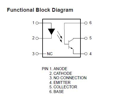
Fig. 4: Pin Diagram of 4N25 Optocoupler
The emitter of the in-built photo-transistor is grounded while the output is drawn from the Collector of the photo-transistor. This way, the photo-transistor actually operates like an LED which gets forward biased when photo-diode glows. The collector pin is connected to pin D2 of the Photon.
Opto-Isolator EL3021:
EL3021 is a photo-TRIAC type opto-coupler. It should be noted that photo-transistor and photo-Darlington type opto-couplers are used for controlling DC devices while photo-SCR and photo-TRIAC type opto-couplers are used for controlling AC devices. The EL3021 has the following pin configuration –
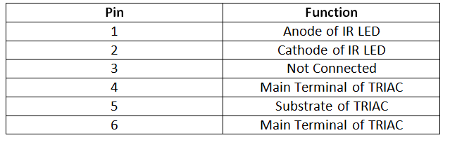
Fig. 5: Table listing pin configuration of EL3021 photo-TRIAC optocoupler
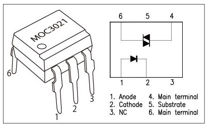
Fig. 6: Pin Diagram of EL3021 photo-TRIAC optocoupler
The pin 2 of EL3021 is connected to ground and pin 1 is connected to pin D5 of the Photon. The Main Terminal pins of photo-TRIAC, pins 4 and 6 of EL3021 are connected to pins 3 (Base) and 2 (Main Terminal 2) of BT136. The pin 2 of BT136 and pin 6 of EL3021 are connected to a junction with phase wire of main supplies. The pin 5 of the EL3021 is not connected so the photo-TRIAC actually operates like a photo-DIAC. The load is connected between pin 1 of BT136 and neutral wire. The phase voltage is controlled by the BT136 which itself is controlled by the photo-TRIAC operating as photo-DIAC of EL3021.
TRIAC BT136:
A TRIAC has three terminals – Main Terminal 1, Main Terminal 2 and Gate. TRIAC is equivalent to two SCRs connected in inverse parallel with the gates connected together. Therefore TRIAC works as a bi-directional switch which is triggered by the pulse on the base. The Main Terminal 1 and Main Terminal 2 of the TRIAC are used for connecting phase and neutral wire and the triggering pulse is supplied to Gate terminal from the photo-TRIAC of EL3021. The Gate terminal can be triggered either by a positive or negative voltage. There are four possible modes in the operation of a TRIAC –
a) Main Terminal 2 has a positive voltage compared to Main Terminal 1 and there is positive pulse at Gate
b) Main Terminal 2 has a positive voltage compared to Main Terminal 1 and there is negative pulse at Gate
c) Main Terminal 1 has a positive voltage compared to Main Terminal 2 and there is positive pulse at Gate
d) Main Terminal 1 has a positive voltage compared to Main Terminal 2 and there is negative pulse at Gate
The TRIAC conducts current when either Main Terminal 2 gets a positive voltage with respect to the Main Terminal 1 and the Gate gets a positive trigger or Main Terminal 1 has a positive voltage compared to Main Terminal 2 and there is negative pulse at Gate. When the Gate current is removed, the TRIAC switches off. BT136 is the TRIAC used in the circuit and has following pin configuration –

Fig. 7: Table listing pin configuration of BT136 TRIAC
How the Circuit Works –

Fig. 8: Prototype of Circuit for AC Voltage Control Over Internet
The Photon is an Arduino compatible IOT board. The code burnt to the board is similar to any Arduino board code. The Particle has provided its own custom libraries for its IOT boards. The project uses a library called Spark Interval Timer Library which runs an interrupt service routine on a fixed interval of time. Each AC cycle has two zero voltage crossing detection. If the frequency of AC mains is 50 Hz then the frequency of zero crossing detection will be 100 Hz and if the frequency of AC mains is 60 Hz then the frequency of zero crossing detection will be 120 Hz.
The AC load taken in the project is a 15 Watt bulb and on controlling AC voltage the project actually behaves like a bulb dimmer. The AC voltage is controlled by a slider on a webpage. There have been 128 steps taken for brightness of the bulb. So if 120 Hz is taken as frequency of zero voltage crossing detection then on taking 128 steps of brightness, the interval for running the interrupt routine will be as follows –
(120 Hz=8333uS) / 128 brightness steps = 65 uS / brightness step
If the AC mains have 50 Hz frequency, so zero voltage crossing has 100 Hz frequency. So if 100 Hz is taken as frequency of zero voltage crossing detection then on taking 128 steps of brightness, the interval for running the interrupt routine will be as follows –
(100Hz=10000uS) / 128 steps = 75uS/ brightness step
So the interrupt service routine should run on 75 uS interval multiplied by the step size selected on the webpage.
The project controls the AC voltage by sending pulses to the Gate pin of BT136 TRIAC. When the circuit is powered ON, the Photon initializes the circuit and waits for data over the internet. The data is received through HTTP POST method using Particle.Function() method and the value of step size is retrieved using Particle.Variable method in a variable “dim”.
The zero voltage crossing is detected by the 4N25 circuit. The AC voltage from main supplies is stepped down to 12V AC by the transformer and rectified by the 1N4007 diode full-wave rectifier. The AC voltage once converted to DC voltage drives the IR diode of 4N25 forward biasing it for voltage levels greater than 1.1 Volt. When voltage level of the rectified wave is above zero voltage crossing, photo-transistor of 4N25 remains in forward biased condition, short circuiting the VCC supply at pin D2 of Photon to ground. Therefore, for majority of the waveform, a LOW logic is received at pin D2 of Photon. When voltage level approaches zero voltage crossing, the IR diode of 4N25 does not get the required voltage for forward biasing. So, the photo-transistor of 4N25 switches to unbiased condition and the pin D2 of Photon get a HIGH pulse upon zero voltage crossing.
The Photon detects the zero voltage crossing and determines a firing angle based on data supplied and step size detected through HTTP POST method. A time interval multiplied by the step size is calculated. An interrupt routine shooting a HIGH pulse for 50 micro-seconds after delay of the resultant time interval is activated at pin D5 of the Photon. The HIGH pulse drives the IR diode of EL3021 opto-coupler with same delay of the calculated time interval. This in turn, drive the triggering pulse at the Gate terminal of BT136 TRIAC with the same delay equivalent to the calculated time interval.
In power control application using TRIAC, the voltage pulse before the emergence of triggering pulse at Gate terminal of TRIAC gets chopped off while the part of AC voltage wave after the emergence of triggering pulse at Gate terminal of TRIAC remains available for supply to the load.
Check out the Photon program which is detecting zero voltage crossing based on digital logic at pin D2, calculating a time delay for triggering pulse by multiplying step size with 75 uS and generating a triggering pulse at pin D5 in an interrupt routine. Check out the HTML code of the webpage which uses a device ID and access token to connect with the Photon board and uses Ajax and JQuery to send HTTP request via POST method to send the step size of the brightness to the board.
Programming Guide –
First the SparkIntervalTimer library is imported to generate time delay. A counter variable is declared and a Boolean type variable to detect zero crossing are declared. A variable is declared to denote pin connecting to the TRIAC and a variable dimming is declared to denote level of brightness. A variable dim is declared which is to be used as multiplier in the time interval. A variable is declared to denote interval for each step and is assigned value 75. An object of interval timer is instantiated.

Fig. 9: Screenshot of Initialization in Particle Photon Code for AC Voltage Control Over Internet
The setup() function is called in which the TRIAC connected pin is set to digital output and an interrupt is attached to pin D2. A variable getpos and function setpos are exposed from the cloud and retrieved through POST method by calling Particle.variable and Particle.function methods.
A zero_cross_int() function is called in which the value of dimming obtained from setPosition function is used to determine time interval and the same delay is generated before triggering pulse at TRIAC pin. Then the pin is set to LOW again.
The setPosition() function retrieve the brightness level from cloud and store it to the dim variable. The value is then assigned to the variable dimming.

Fig. 10: Screenshot of Setup and Loop Functions in Particle Photon Code for AC Voltage Control Over Internet
Note: The complete Photon Code for AC Voltage Control Over Internet Project can be found in the source code tab.
For controlling the AC voltage over internet, a webpage needs to be created. The webpage will have the following HTML and Javascript embedded inline.
The doctype is declared for setting the page to HTML 5 version and head element is added. Inside the head element, character set is defined utf-8 and the webpage is set to span over entire window. The bootstrap for CSS and Javascript is included from CDN using the link element.
The body element is declared and an additional division element is declared to hold the content of webpage. The webpage is structured through other division elements and some headers paragraph buttons and datalist elements are added.
The javascript is embedded in which the device ID and accesstoken are declared as variables and a function to return time interval according to the value of datalist element is defined. The elements on the page are accessed through javascript function getElementbyID. The JSON ended data is retrieved though HTTP GET method by using $.JSON method and $.Post method is used to retrieve data from the cloud using HTTP POST method.

Fig. 11: Screenshot of Source Code of Webpage controlling AC Voltage
This is HTML code that needs to be run for sending data to Particle’s Cloud service. The cloud service automatically connects to the Photon and Code on Photon operates according to the data received from cloud.
Note: The required HTML file can be found in the attachment below.
Project Source Code
###
//Program to // This #include statement was automatically added by the Particle IDE. #includevolatile int i=0; // Variable to use as a counter volatile boolean zero_cross=0; // Boolean to store a "switch" to tell us if we have crossed zero int AC_LOAD = D5; // Output to Opto Triac int dimming = 0; // Dimming level (0-128) 0 = on, 128 = 0ff int dim; // counting up or down, 1=up, -1=down int freqStep = 75; // This is the delay-per-brightness step in microseconds. IntervalTimer myTimer; void setup() { pinMode(AC_LOAD, OUTPUT);// Set AC Load pin as output attachInterrupt(D2, zero_crosss_int, RISING); // Choose the zero cross interrupt # from the table above Particle.function("setpos", setPosition); Particle.variable("getpos", &dim, INT); } void zero_crosss_int() // function to be fired at the zero crossing to dim the light { int dimtime = (freqStep*dimming); // For 60Hz =>65 delayMicroseconds(dimtime); // Off cycle digitalWrite(AC_LOAD, HIGH); // triac firing delayMicroseconds(10); // triac On propagation delay (for 60Hz use 8.33) digitalWrite(AC_LOAD, LOW); // triac Off } void loop() { } int setPosition(String incValue) { dim = incValue.toInt(); dimming = dim; return 0; } ###
Circuit Diagrams
| Circuit-Diagram-Zero-Voltage-Crossing-Detector_0 |  |
| Circuit-Diagram-Particle-Photon-AC-Voltage-Control-IOT-Project | 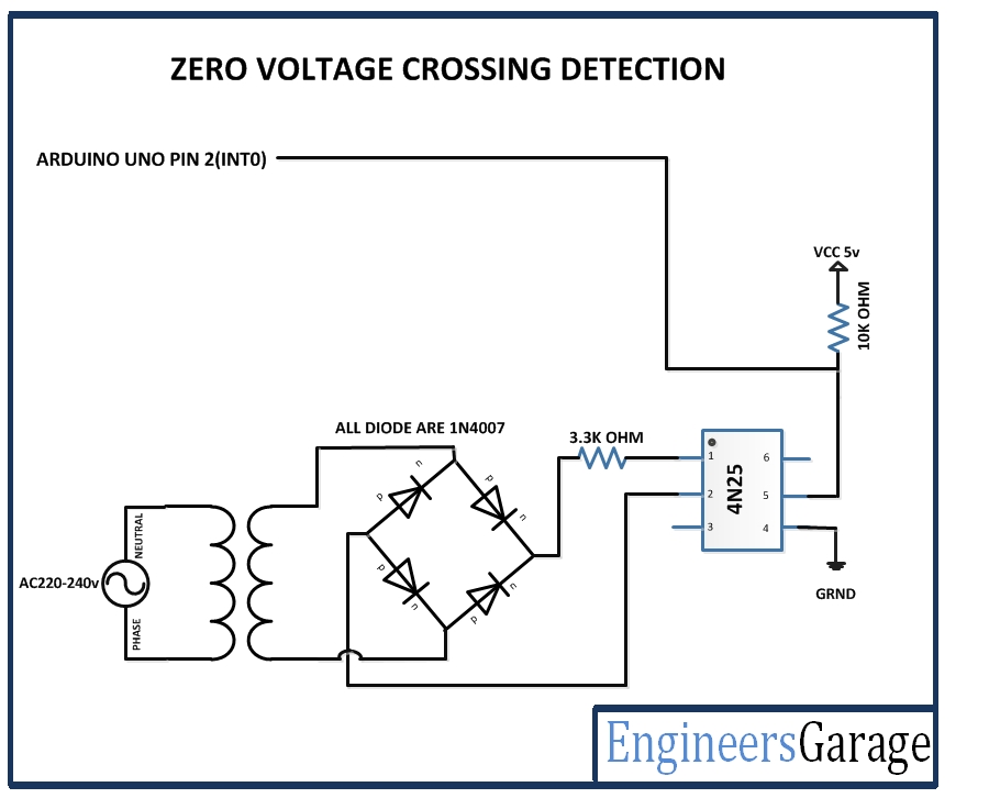 |
Project Video
Filed Under: Electronic Projects
Filed Under: Electronic Projects


Questions related to this article?
👉Ask and discuss on EDAboard.com and Electro-Tech-Online.com forums.
Tell Us What You Think!!
You must be logged in to post a comment.