Engineers Garage

  • Electronic Projects & Tutorials
    • Electronic Projects
      • Arduino Projects
      • AVR
      • Raspberry pi
      • ESP8266
      • BeagleBone
      • 8051 Microcontroller
      • ARM
      • PIC Microcontroller
      • STM32
    • Tutorials
      • Audio Electronics
      • Battery Management
      • Brainwave
      • Electric Vehicles
      • EMI/EMC/RFI
      • Hardware Filters
      • IoT tutorials
      • Power Tutorials
      • Python
      • Sensors
      • USB
      • VHDL
    • Circuit Design
    • Project Videos
    • Components
  • Articles
    • Tech Articles
    • Insight
    • Invention Stories
    • How to
    • What Is
  • News
    • Electronic Product News
    • Business News
    • Company/Start-up News
    • DIY Reviews
    • Guest Post
  • Forums
    • EDABoard.com
    • Electro-Tech-Online
    • EG Forum Archive
  • DigiKey Store
    • Cables, Wires
    • Connectors, Interconnect
    • Discrete
    • Electromechanical
    • Embedded Computers
    • Enclosures, Hardware, Office
    • Integrated Circuits (ICs)
    • Isolators
    • LED/Optoelectronics
    • Passive
    • Power, Circuit Protection
    • Programmers
    • RF, Wireless
    • Semiconductors
    • Sensors, Transducers
    • Test Products
    • Tools
  • Learn
    • eBooks/Tech Tips
    • Design Guides
    • Learning Center
    • Tech Toolboxes
    • Webinars & Digital Events
  • Resources
    • Digital Issues
    • EE Training Days
    • LEAP Awards
    • Podcasts
    • Webinars / Digital Events
    • White Papers
    • Engineering Diversity & Inclusion
    • DesignFast
  • Guest Post Guidelines
  • Advertise
  • Subscribe

AC Voltmeter with Digital Display

By Harwinder Harry April 21, 2008


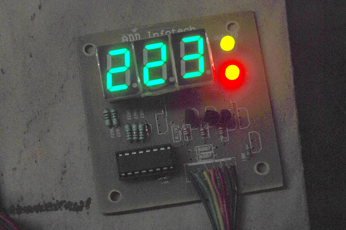
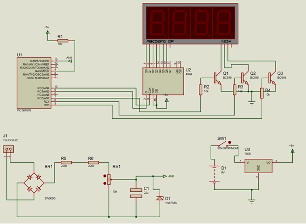
In Electronic field voltmeters have found an essential place, Voltmeters are of two types AC &DC and here I have demonstrated a working AC Voltmeter. It has a large range from 0V to 1000V.The output is shown on 7 segment display .I have used a PIC 16f676 microcontroller .The main part of this AC voltmeter project are ::-

1)     Converting Circuit (For converting Ac to dc in range of 0-5V)

2)      ADC Interfacing(10 bit Inbuilt ADC of 16F676)

3)      7 Segment Multiplexing


Converting Circuit:-


AC Voltmeter Converting Circuit


It has bridge rectifier which is made from diodes In4007.It convert Ac Voltage to Dc Voltage. Next is Voltage divider circuit which converts any voltage from 0 to 1000v to 0 to 5v range. It is made using two resistors and a potential meter in series. Next capacitor is used for removing ripples .the zener 5.1V is used for protection it will never give voltage to controller more than 5.1 V. 

PIC 16F676:-

Introduction to Pic16f676:- Pic 16f676 is 8 bit microcontroller from microchip .It comes in 14 pin dip Package .It has 12 I/O pin for external device interface. The I/O pins have high current sink and source capacity so that they can drive led directly. It has analog comparator module with one analog comparator. It has on 8 bit timer and one 16 bit timer. It has wide frequency range from dc to 20 MHZ. It has also an external interrupt pin for external hardware interrupts.

PIC 16F676

PIC Pin Diagram

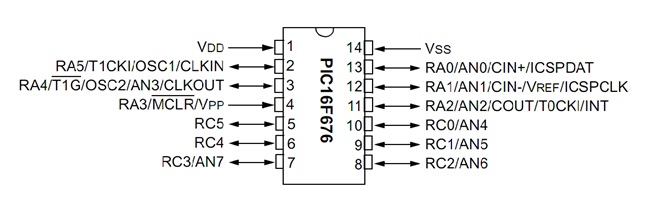
PIN DIAGRAM OF 16F676

 PIC 16F76

Some Features Of 16f676:­-

·         Internal 4MHZ oscillator so need of external crystal(For this project).

·         Wide operating voltage range 2v to 5v

·         10 bit 8 channel inbuilt ADC 


Let us know how to use inbuilt ADC.16f676’sADCs have three main register as given below:-

·         ADCON0

·         ADCON1

·         ANSEL


ADCON0:-

Bit 7

Bit 6

Bit 5

Bit 4

Bit 3

Bit 2

Bit 1

Bit 0

ADFM

VCFG

–

CHS2

CHS1

CHS0

GO/DONE

ADON


ADFM:- 0 Left justified(used when only 8 bit result is need)

               1 Right justified(used when 10 bit result is required so I am use this)


VCFG:  reference voltage set bit

0 =VDD(I have use this option)

1=Vref  pin

ADC result can be find as:

Reading=(Vin.1024)/Vref


CHS2…CHS0: Used for selecting particular ADC channel

000=AN0(channel 0), 001=AN1(channel 1),……….. 111=AN7(channel 7)


GO/DONE:- writing 1 to this bit start conversion. When conversion completes it clear by hardware. So in program we have to first set this and then monitor this to find when conversion will  complete. 


ADON:- 0 ADC OFF

1=ADC ON


ADCON1:–

Bit 7

Bit 6

Bit 5

Bit 4

Bit 3

Bit 2

Bit 1

Bit 0

–

ADCS2

ADCS1

ADCS0

–

–

–

–


ADCS2..S0: These bits are used for selecting clock source for ADC As given below:-

000=Fosc/2,

001=Focs/8

010=Fosc/32

X11=Frc(internal oscillator .I have chase this option)

100=Fosc/4,

101=Focs/16

110=Fosc/64


ANSEL;-


Bit 7

Bit 6

Bit 5

Bit 4

Bit 3

Bit 2

Bit 1

Bit 0

ANS7

ANS6

ANS5

ANS4

ANS3

ANS2

ANS1

ANS0


ANS0…7:-

1=Analog channel;

0=Digital I/O

So by this we have to select that which pin of PORTA we want to use analog input and which are using as digital I/O. For PORT as I/O TRISX is also used here  X is Port name like A,B,C .For input you have to move 1 to corresponding bit of TRIS register and 0 for as output.

So by moving particular value in these registers now you can use ADC of 16f676.Next step is 7 segment display multiplexing. 

 7 Segment Multiplexing

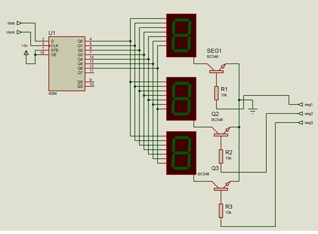
7 Segment Multiplexing:-The connection for 7 segments are shown in circuit diagram tab1:-

I have  used an extra ic 4094.it is  shift register it I used t increase the no. of pins. Here I will shift 8 bit data serially using two pins data and cock. The steps for 7 segment multiplexing:-

         1) Off all segment (seg1=0, seg2=0, seg3=0)

         2) Shift the data of first segment

         3) On the first segment(seg1=1;)

         4) Delay 1 ms

         5) Off first segment(seg1=0;)

         6) Shift the data of second segment

         7) On the second segment(seg2=1;)

         8) Delay 1 ms

         9) Off second  segment(seg2=0;)

       10) Shift the data of third segment

       11) On the third segment(seg3=1;) 

       12) Delay 1 ms

       13) Off third segment(seg3=0;)

       14) Go to first step and repeat it again and again

So now I have explain all things now it is time to give final circuit diagram which is shown in circuit diagram tab2.

Note: -For using internal oscillator you have to set some fuse bits while programming ic. If you are facing any problem regarding these bits you can us external crystal of 4MHz. 

Conclusion

Conclusion:-   I have made this ac voltmeter for my lab. I Found that it is accurate but due to fluctuation in ac voltage will not stable on it changes by 2 to 5 volt. so to stable this we can change the program little bit that take the 10 reading and display the average of these readings. We can also measure the dc voltage also with this by direct connecting the dc voltage to output of bridge. So its not a AC voltmeter only you can also measure dc as well. If we connect directly DC  to AC leads of this then drop across 1n4007 ld to error reading because drop across diode is 07v volt which is much higher.

AC Voltmeter

Digital Display AC Voltmeter


Project Source Code


Project Source Code

###


   #define data1 PORTC.F1

7-Segment-intefacing
Circuit-Diagram


Filed Under: Electronic Projects
Tagged With: ac, display, pic 16f76, voltmeter
 

Next Article

← Previous Article
Next Article →

Comments

  1. [email protected] says

    July 8, 2024 at 3:02 am

    Where is code for this ?

    Log in to Reply

Questions related to this article?
👉Ask and discuss on Electro-Tech-Online.com and EDAboard.com forums.


Tell Us What You Think!! Cancel reply

You must be logged in to post a comment.

EE TECH TOOLBOX

“ee
Tech Toolbox: 5G Technology
This Tech Toolbox covers the basics of 5G technology plus a story about how engineers designed and built a prototype DSL router mostly from old cellphone parts. Download this first 5G/wired/wireless communications Tech Toolbox to learn more!

EE Learning Center

EE Learning Center
“engineers
EXPAND YOUR KNOWLEDGE AND STAY CONNECTED
Get the latest info on technologies, tools and strategies for EE professionals.

HAVE A QUESTION?

Have a technical question about an article or other engineering questions? Check out our engineering forums EDABoard.com and Electro-Tech-Online.com where you can get those questions asked and answered by your peers!


RSS EDABOARD.com Discussions

  • Single ended measuring ports and balanced antenna
  • Right Half Plane Zero
  • Thermal modelling of repetitive power pulse
  • Testing 5kW Grid Tied inverter over 200-253VAC
  • Resistor Selection for Amplifier Layout

RSS Electro-Tech-Online.com Discussions

  • Fun with AI and swordfish basic
  • Can I make two inputs from one??
  • Simple LED Analog Clock Idea
  • Is AI making embedded software developers more productive?
  • Behlke swich

Featured – LoRa/LoRaWan Series

  • What is the LoRaWAN network and how does it work?
  • Understanding LoRa architecture: nodes, gateways, and servers
  • Revolutionizing RF: LoRa applications and advantages
  • How to build a LoRa gateway using Raspberry Pi
  • How LoRa enables long-range communication
  • How communication works between two LoRa end-node devices

Recent Articles

  • RPi Python Programming 21: The SIM900A AT commands
  • RPi Python Programming 22: Calls & SMS using a SIM900A GSM-GPRS modem
  • RPi Python Programming 23: Interfacing a NEO-6MV2 GPS module with Raspberry Pi
  • RPi Python Programming 24: I2C explained
  • RPi Python Programming 25 – Synchronous serial communication in Raspberry Pi using I2C protocol

EE ENGINEERING TRAINING DAYS

engineering

Submit a Guest Post

submit a guest post
Engineers Garage
  • Analog IC TIps
  • Connector Tips
  • Battery Power Tips
  • DesignFast
  • EDABoard Forums
  • EE World Online
  • Electro-Tech-Online Forums
  • EV Engineering
  • Microcontroller Tips
  • Power Electronic Tips
  • Sensor Tips
  • Test and Measurement Tips
  • 5G Technology World
  • Subscribe to our newsletter
  • About Us
  • Contact Us
  • Advertise

Copyright © 2025 WTWH Media LLC. All Rights Reserved. The material on this site may not be reproduced, distributed, transmitted, cached or otherwise used, except with the prior written permission of WTWH Media
Privacy Policy

Search Engineers Garage

  • Electronic Projects & Tutorials
    • Electronic Projects
      • Arduino Projects
      • AVR
      • Raspberry pi
      • ESP8266
      • BeagleBone
      • 8051 Microcontroller
      • ARM
      • PIC Microcontroller
      • STM32
    • Tutorials
      • Audio Electronics
      • Battery Management
      • Brainwave
      • Electric Vehicles
      • EMI/EMC/RFI
      • Hardware Filters
      • IoT tutorials
      • Power Tutorials
      • Python
      • Sensors
      • USB
      • VHDL
    • Circuit Design
    • Project Videos
    • Components
  • Articles
    • Tech Articles
    • Insight
    • Invention Stories
    • How to
    • What Is
  • News
    • Electronic Product News
    • Business News
    • Company/Start-up News
    • DIY Reviews
    • Guest Post
  • Forums
    • EDABoard.com
    • Electro-Tech-Online
    • EG Forum Archive
  • DigiKey Store
    • Cables, Wires
    • Connectors, Interconnect
    • Discrete
    • Electromechanical
    • Embedded Computers
    • Enclosures, Hardware, Office
    • Integrated Circuits (ICs)
    • Isolators
    • LED/Optoelectronics
    • Passive
    • Power, Circuit Protection
    • Programmers
    • RF, Wireless
    • Semiconductors
    • Sensors, Transducers
    • Test Products
    • Tools
  • Learn
    • eBooks/Tech Tips
    • Design Guides
    • Learning Center
    • Tech Toolboxes
    • Webinars & Digital Events
  • Resources
    • Digital Issues
    • EE Training Days
    • LEAP Awards
    • Podcasts
    • Webinars / Digital Events
    • White Papers
    • Engineering Diversity & Inclusion
    • DesignFast
  • Guest Post Guidelines
  • Advertise
  • Subscribe