This Project is sent by Mr. Saif Ullah Qureshi from UET,Lahore, Pakistan
Introduction:
In our daily life, anything we deal like sound, pressure, voltage or any measurable quantity, are usually in analog form. So what if we want to interface any analog sensor with our digital controllers? There must be something that translate the analog inputs to digital output, and so Analog to digital convertors come to play. Usually we call them ADC (Analog to digital convertor). Before going to learn how to interface an ADC with a controller we first take a look at basic methods of analog to digital conversion.
An analog-to-digital converter (abbreviated ADC, A/D or A to D) is a device which converts a continuous quantity to a discrete timedigital representation. An ADC may also provide an isolated measurement. The reverse operation is performed by a digital-to-analog converter (DAC).Typically, an ADC is an electronic device that converts an input analog voltage or current to a digital number proportional to the magnitude of the voltage or current. However, some non-electronic or only partially electronic devices, such as rotary encoders, can also be considered ADCs.
The digital output may use different coding schemes. Typically the digital output will be a two’s complement binary number that is proportional to the input, but there are other possibilities. An encoder, for example, might output a Gray code.
Sampling rate:
The analog signal is continuous in time and it is necessary to convert this to a flow of digital values. It is therefore required to define the rate at which new digital values are sampled from the analog signal. The rate of new values is called the sampling rate or samplingfrequency of the converter.
A continuously varying bandlimited signal can be sampled (that is, the signal values at intervals of time T, the sampling time, are measured and stored) and then the original signal can be exactly reproduced from the discrete-time values by an interpolation formula. The accuracy is limited by quantization error. However, this faithful reproduction is only possible if the sampling rate is higher than twice the highest frequency of the signal
Since a practical ADC cannot make an instantaneous conversion, the input value must necessarily be held constant during the time that the converter performs a conversion (called the conversion time). An input circuit called a sample and hold performs this taskin most cases by using a capacitor to store the analog voltage at the input, and using an electronic switch or gate to disconnect the capacitor from the input. Many ADC integrated circuits include the sample and hold subsystem internally as shown in figure in the next page.

Components used:
1. AT89c51 microcontroller
2. A Resister (470 Ohm)
3. A LED (yellow color)
Descriptions about components:
AT89C51:
Visit the links for details about the AT89C51 Microcontroller:
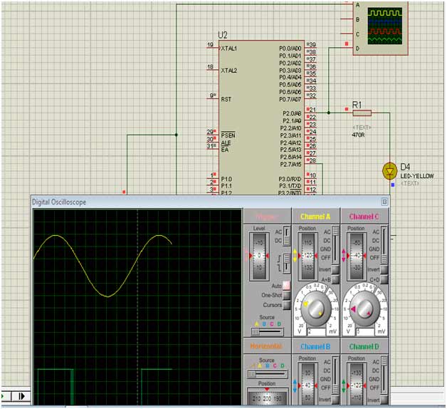
Oscillioscope:
When we give input to the circuit in the form of sinesuidal wave in the form of a.csignal.Then we will take output from circuit through the oscillioscope,it will show the output waveform as a square waveform as shown in above figure.
Resistor:
The value of resistor is adjustedso that the rating of the led which is connected in the circuit . If the value of resistance will very high then the blinkness of led is for very short timing and we could not see the output clearly. So we should keep this value very low or of medium value so that the output can see clearly.
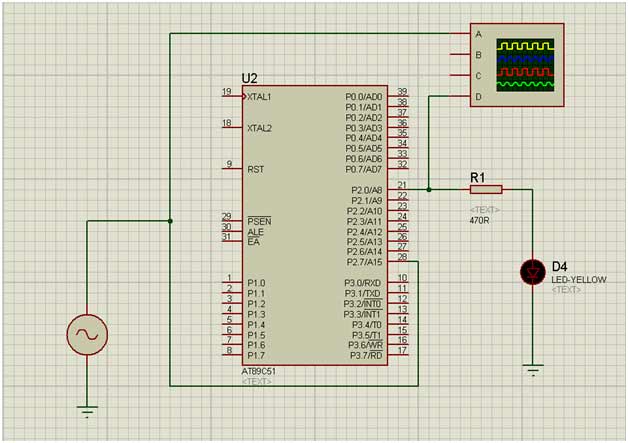
Circuit Diagram:
Code:
The C Language Code for the analogue to digital converter is very simple which is give below:
sbit output1 = 0xA0; //P2_0;sbit input1 = 0xA7; //P2_7;void test();void main(){test()}void test(){output1=input1;test();}
OutPut :
In this plotting of oscillioscope sine wave is the input and square waveform is the output ,and in circuit diagram led is represented the output.
Difficulties faced during this project :-
We have a variety of projects for analogue to digital converter but we prefer this project because in the engineering point of view the cost of the products should be minimum.as in this project we simply used the microcontroller At89c51, one resistor and one led. Further,we can perform this project without microcontroller (At89c51)but the output was of not exact square waveform. So we used it just for the sake of creating pure square waveform.
Filed Under: Electronic Projects

Questions related to this article?
👉Ask and discuss on EDAboard.com and Electro-Tech-Online.com forums.
Tell Us What You Think!!
You must be logged in to post a comment.