Inertial sensors are used to detect linear and rotational motion of an object. There are two types of inertial sensors – accelerometers that detect linear acceleration and gyroscopes that detect rotational motion. Accelerometers and gyros are widely used in several applications, including aerospace, military, automotive, mobile phones, and consumer electronics. For example, in mobile phones, gyroscope and accelerometer sensors are used for screen rotation, gaming, virtual reality, and augmented reality applications. In automobiles, accelerometer and gyroscope are used for detection vehicle rollover, airbag release control, ABS, active suspension, traction control, and seat belt control. Many military applications like smart ammunition, flight control, etc. also make use of these sensors. In aerospace applications, these sensors are used for measuring microgravity and monitoring the movement and rotation of equipment/devices.
Each application requires an accelerometer or gyroscope with particular specifications. No one accelerometer or gyroscope sensor can fit all applications. These sensors are always used in some electronic control systems as mere values of acceleration and rotation of an object are of no use.
ADXL345 is a small 3-axis accelerometer that a dynamic range of +/-16g with 13-bit resolution, the maximum bandwidth of 3200Hz, and a maximum data transfer rate of 3200 times a second. It is a digital accelerometer sensor and outputs digital values of acceleration in three axes. The sensor outputs data formatted as 16-bit two’s complement that is accessible via SPI or I2C interfaces. This sensor is ultra-low power and consumes only 23 uA in measurement mode and 0.1 uA in standby mode.
ADXL345 has user-selectable resolution and measurement ranges that can be selected by passing serial commands to it. The sensor also supports flexible interrupt modes that can be mapped to either of its two interrupt pins. ADXL345 has several built-in sensing functions that can be mapped to the interrupt pins. Like, It has free-fall detection and tap detection functions. ADXL345 can detect the presence or lack of motion by comparing acceleration values to user-defined thresholds.
ADXL345 measures static acceleration due to gravity as well as dynamic acceleration resulting from motion or shock. The sensors come in a 14-lead LGA package having just 3mm x 5 mm x 1 mm dimensions. This sensor can be used in mobile device applications like mobile handsets, smartphones, gaming devices, pointing devices, personal navigation devices, hard drive protection, medical and industrial instrumentation.
Understanding ADXL345 technical specification
The ADXL345 accelerometer sensor has the following technical specifications –
Measurement range – ADXL345 sensor can measure acceleration in three axes using a user-selectable range of +/-2g, +/-4g, +/-8g, and +/-16g. Higher is the measurement range, higher the acceleration an accelerometer can sense. With a measurement range of +/-2g selected, ADXL345 can measure acceleration up to 19.6 m/s2 (2 * 9.8 m/s) in either direction along each axis. With a measurement range of +/-16g selected, ADXL345 can measure acceleration up to 153.6 m/s2 (16 * 9.8 m/s) in either direction along each axis.
Output Resolution – ADXL345 supports output resolution of 10-bit for +/- 2g measurement range, 11-bit for +/- 4g, 12-bit for +/- 8g and 13-bit for +/- 16g. The default resolution is 10-bit for all measurement ranges.
Sensitivity – With the default resolution of 10-bit, the ADXL345 has typical sensitivity of 3.9 mg/LSB for default measurement range (i.e. +/- 2g), 7.8 mg/LSB for +/- 4g, 15.6 mg/LSB for +/- 8g and 31.2 mg/LSB for +/- 16g measurement range. This means that ADXL345 with default 10-bit resolution selected can detect minimum change of acceleration of 3.822 cm/s2 (3.9 * 9.8/1000 * 100) for +/- 2g, 7.64 cm/s2 for +/- 4g, 15.28 cm/s2 for +/- 8g, and 30.57 cm/s2 for +/- 16g range.
Output data rate and bandwidth – The output data rate and bandwidth of the sensor is selectable. The output data rate can range from 0.1 Hz (once in 10 seconds) to 3200 Hz (3200 times a second).
Operating voltage and current – The sensor requires an operating voltage of 2.5V that can range from 2.0V to 3.6V. It consumes approximately 30 uA for a data transfer rate less than 10 Hz and around 140 uA for data transfer rates above 100 Hz.
Operating temperature range – ADXL345 has an operating temperature range of -40˚C to +85˚C.
Maximum Ratings – ADXL345 can tolerate shock or acceleration up to 10,000 g (98 km/s2). It can tolerate voltage up to 3.9V and withstand temperature up to +105˚C.
ADXL345 Pin description
ADXL345 comes in a 14-lead package having the following pin diagram:
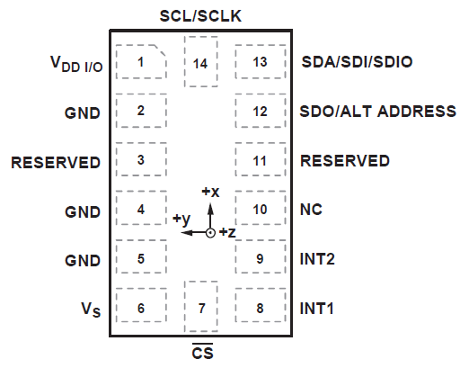
ADXL345 Accelerometer sensor has the following pin description:

The sensor may be available as a module where all or few pins may be available for interfacing with a circuit. In the sensor module shown below, only pins necessary for interfacing with a circuit (I2C, SPI, Interrupts, and power supply) are available for use. Other pins are hard-wired on the module like with pull-up resistors for I2C lines.
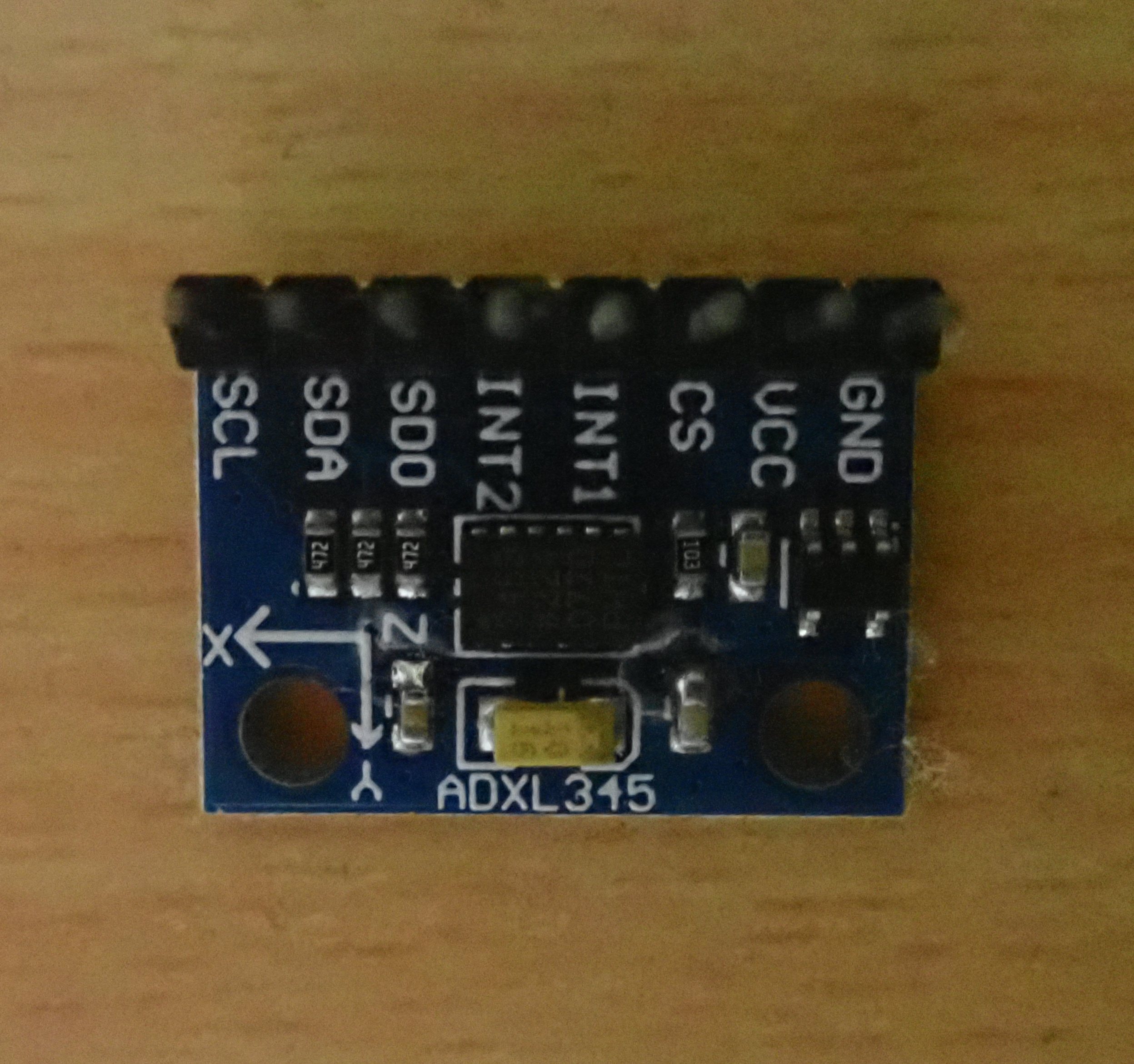
It can be noted that axes of acceleration are indicated on the module. Otherwise, the axes of accelerations can be found with respect to the top view of the sensor, as shown below:
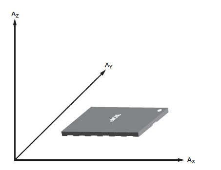
Example of ADXL345 accelerometer sensor axis.
The ADXL345 sensor is sensitive to both static acceleration (acceleration due to gravity) as well as dynamic acceleration (acceleration resulting from motion or shock). The sensor has the output response, as shown in the image below, with respect to its orientation to gravity.
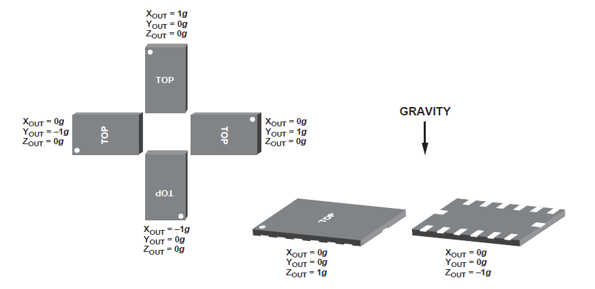
ADXL345 output response with respect to orientation to gravity.
Performance characteristics of ADXL345
The performance characteristics of ADXL345 are available as graphs for Zero-g offset, sensitivity, and self-test response. The graphs are given for sensor response for all axes. For example, the following graph shows Zero-g offset in x-axis at 25˚C, 2.5V.
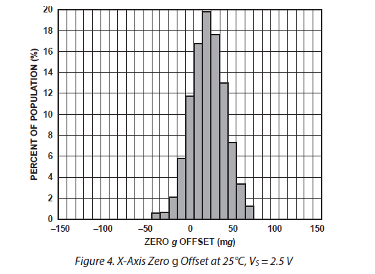
ADXL345 performance characteristics
In the graph, the Zero-g offset is indicated in mg (0.98 cm/s2), and percent of the population indicates the percent of samples of the sensor under test. Similarly, sensitivity is shown as the number of LSBs per g for each axis.
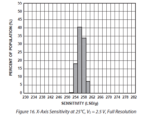
ADXL345 performance characteristics.
With the output resolution of ADXL345 being default to 10-bit, we can conclude that the change in acceleration of the object to which the ADXL345 is mounted must be at least 3.822 cm/s2 for +/- 2g or 7.64 cm/s2 for +/- 4g or 15.28 cm/s2 for +/- 8g or 30.57 cm/s2 for +/- 16g measurement range for 1-bit (LSB) change in the sensor response.
How ADXL345 sensor works
ADXL345 is a 3-axis accelerometer that senses both static acceleration (due to gravity) as well as dynamic acceleration (due to motion or shock). So, it can be used as a tilt sensor or to detect free fall. It is a MEMS accelerometer consisting of a polysilicon surface-micro-machined structure built on the top of a Polysilicon wafer. It is a capacitive accelerometer sensor. The polysilicon springs suspend the proof mass, and differential capacitors are used between the proof mass and fixed frame to measure the acceleration. Any acceleration along an axis deflects the proof mass and unbalances the differential capacitor, resulting in a sensor response that is directly proportional to the acceleration. Phase-sensitive demodulation is used to determine the magnitude and polarity of the acceleration.
The sensor can be interfaced with a controller/embedded computer using I2C or SPI interface. Using serial interfaces (I2C/4-wire SPI/3-wire SPI), a controller/computer can read and write to internal registers of the sensor. ADXL345 has the following functional block diagram.
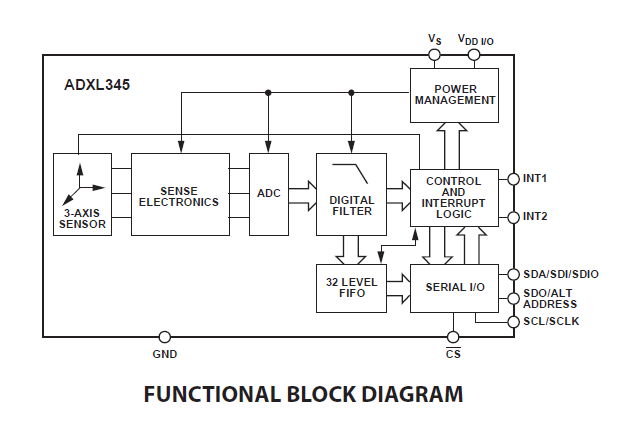
Functional block diagram of the ADXL345 accelerometer sensor.
The sensor has the following registers to which a controller/computer can read/write over serial interfaces:
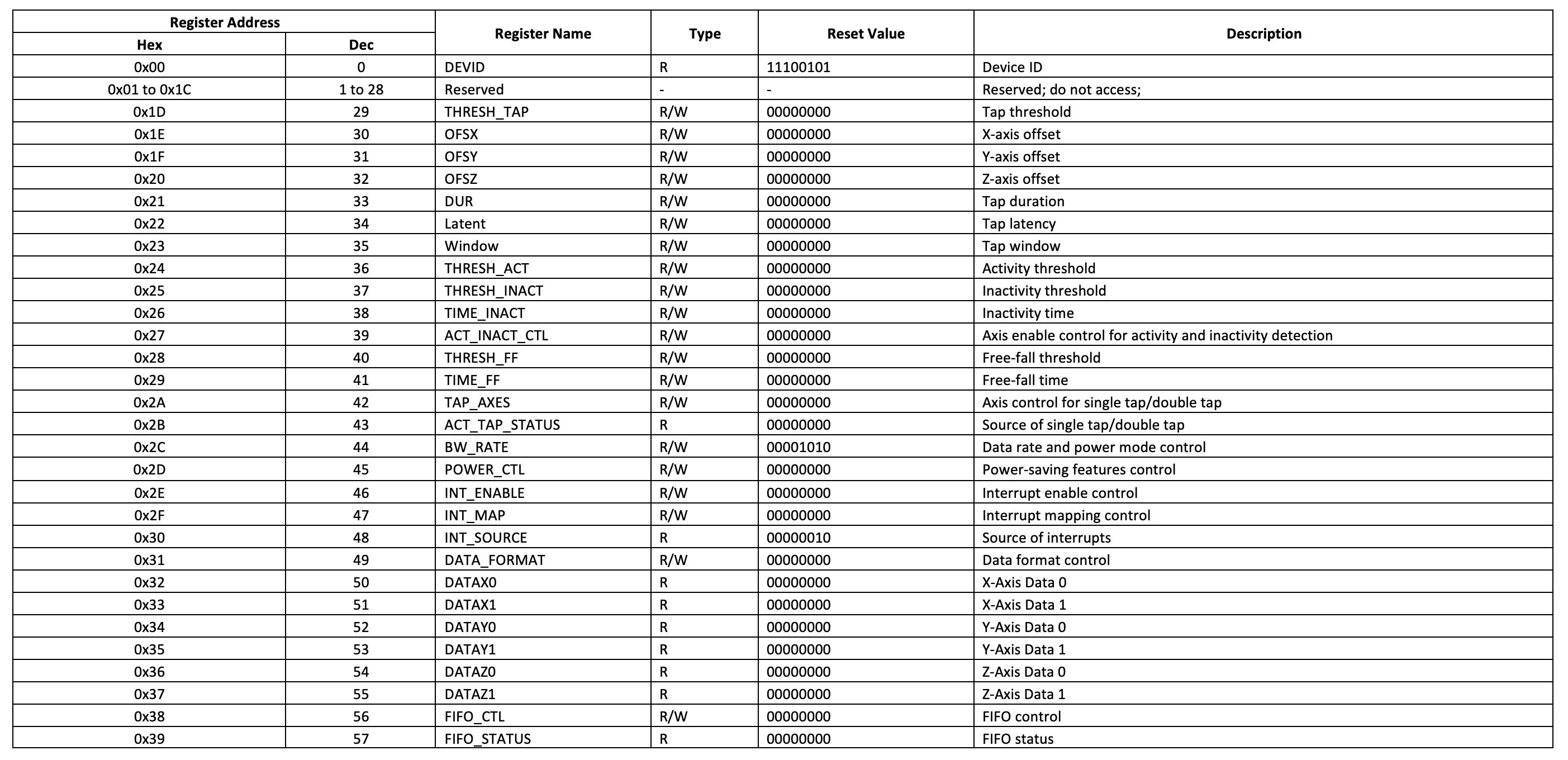 By writing data to the registers, the controller/computer can select measurement range, data format, resolution, and control interrupts and sensing functions (tapping, free-fall, and thresholds). A controller/computer can read acceleration by reading values from registers 0x32 to 0x37.
Configuring ADXL345 and reading acceleration values
Below are listed a few simple steps to read acceleration from the ADXL345 sensor.
- Set power mode and data transfer rate by writing to the 0x2C register. This register has the following bits:
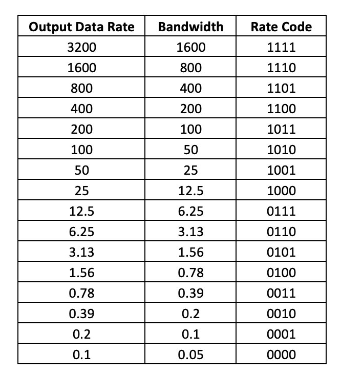
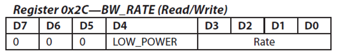 If LOW_POWER bit is set to 0, the ADXL345 works in normal mode, and if it is set to 1, ADXL345 works in reduced power modes, in which there is higher noise. The bits D3 to D0 selects the data transfer rate according to the following table:
- Set the data format by writing to the 0x31 register. This register has the following bits:
 If the SELF-TEST bit is set to 1, a self-test force is applied to the sensor, causing a shift in the output data. If it is set to 0, the self-test force is disabled. If SPI bit is set to 1, ADXL345 uses 3-wire SPI mode; otherwise, if set to 0, it uses 4-wire SPI mode. If INT_INVERT bit is set to 0, it sets the interrupts to active high, and if it is set to 1, it sets the interrupts to active low. If FULL_RES bit is set to 1, the sensor outputs full-resolution value (10-bit for +/- 2g; 11-bit for +/-4g; 12-bit for +/- 8g; 13-bit for +/- 16g) otherwise if it is set to 0, default 10-bit is used. If the justify bit is set to 1, acceleration values in registers 0x32 to 0x37 are left-justified; otherwise, if it is set to 0, values are right-justified. The following image shows the data format of data-value registers with left and right justification and position of LSB or MSB accordingly for different measurement range:
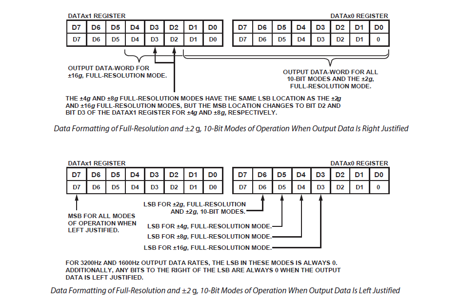
Examples of left- and right-justified output response of the ADXL345 accelerometer sensor.
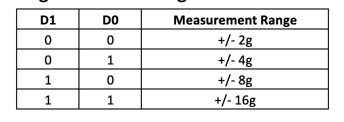
The range bits D1 and D0 selects the measurement range according to the following table:
- If the link bit is set to 1, activity and inactivity functions are serially linked (activity function is delayed until inactivity function is detected). Otherwise, if it is set to 0, both functions are concurrent. The inactivity function refers to a situation when acceleration is below the THRESH_INACT value (0x25 register) for at least the time indicated by TIME_INACT (0x26 register).Set power-saving features by writing to the 0x2D register. This register has the following bits:
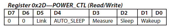 If the link bit is set and the AUTO_SLEEP bit is set to 1, it enables the auto-sleep functionality. In this mode, the ADXL345 automatically switches to sleep mode if the inactivity function is enabled and inactivity is detected. If activity is also enabled, the ADXL345 automatically wakes up from sleep after detecting activity and returns to operation at the output data rate set in the BW_RATE register. If the AUTO_SLEEP bit is set to 0, it disables automatic switching to sleep mode. If the link bit is not set, the AUTO_SLEEP feature is disabled, and setting the AUTO_SLEEP bit does not have an impact on device operation.
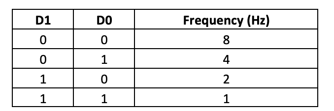
If Measure bit is set to 1, ADXL345 operates in measurement mode. Otherwise, if it is set to 0, ADXL345 operates in standby mode. If Sleep bit is set to 1, ADXL345 operates in sleep mode; otherwise, if it is set to 0, ADXL345 operates in normal mode. Sleep mode suppresses DATA_READY, stops transmission of data to FIFO, and switches the sampling rate to one specified by the wakeup bits. In sleep mode, only the activity function can be used. The wake-up bits control the frequency of reading in sleep mode according to the following table:
- Read acceleration along the x-axis by reading registers 0x32 and 0x33; acceleration along Y-axis by reading registers 0x34 and 0x35; and acceleration along Z-axis by reading registers 0x36 and 0x37.
Mask the register values according to the selected data format (0x31 register) and interpret the value of acceleration according to the selected measurement range.
Using acceleration values from ADXL345
The acceleration values along X-, Y- and Z- axis from the ADXL345 accelerometer sensor can be used to detect tilt, free-fall, and dynamic motion of an object. The sensor must be mounted to the object under study. The acceleration values can be used simply to detect motion or even to determine the trajectory of the object.
The velocity along each axis can be determined by integration of the acceleration values. The double-integration of the acceleration values can determine the displacement of the object along each axis. It should be noted that integration and double-integration of acceleration values can be done only using scientific computing tools like the SciPy library in Python scripts. Even then, we have to consider errors as there can be multiple sources of error like an inconsistent sampling of data, errors in sampled data, errors due to computing, etc. Generally, displacement or velocity values can be predicted to limited accuracy and to a limited range in a user program with the ADXL345 sensor.
However, the acceleration values from the ADXL345 sensor can be perfectly used in electronic control systems where mere values of acceleration are utilized for decision-making.
You may also like:


Filed Under: Electronic Projects

Questions related to this article?
👉Ask and discuss on Electro-Tech-Online.com and EDAboard.com forums.
Tell Us What You Think!!
You must be logged in to post a comment.