In today’s busy life this circuit plays a vital role, as u doesn’t need to waste your important time to check your mail box.
Circuit also consumes less electric power as it works on only 9V of power supply.
At the time new mail arrives at your box a red colour LED will flash, otherwise a green led is on.
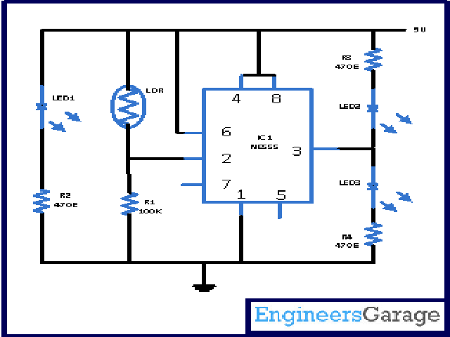
When there is no mail in your box then at the instance of time, LDR gets light from LED1. As a result of it there is low resistance on LDR and there will be no output from IC.
While when a new mail arrives, resistance of LDR reaches to high because no light form LED1 reaches to LDR. And as a result of it we will get output from LDR.
Principle behind Circuit-
This circuit is constructed with the help of much known IC NE555. In this circuit this IC work like a comparator. Pin 6 of the IC is lined with positive power supply. When pin 2 is less than 1/3 of the applied voltage output at pin 3 is high. Similarly the output will low when voltage at pin is higher than 1/3 of applied voltage. So the output in the circuit remain only in two state either high or low. Pin 1 of IC is grounded while pin 4 and 8 is coupled with positive supply.
To sense the arrival of new mail LDR is used along with source of light (ie LED1 in this circuit). LDR response depends upon the amount of light fall on it. At light time resistance of LDR vary from 2-5 K. And in the absence of light it will be around 1megaohm.
Circuit is assemble is such a manner that the light of LED1 will directly fall on LDR. But at the time when new letter arrives, the light beam will blocked and LDR goes into darkness.
Now when there is no mail in the box then light of LED1 continuously fall on LDR, pin 2 of IC remains on high and LED2 will glow which is connected in the reverse bias mode. As soon as new mail arrives in the mail box light beam from LED1 could not reach to LDR as letter is between them. At this condition voltage at pin 2 of IC drops which in turns makes the pin 3 at high voltage. At this condition LED3 will glow which is connects in the forward bias state.
In place of LED3 you can also use any sound bell or speaker.
Circuit Diagrams
Project Components
Filed Under: Circuit Design


Questions related to this article?
👉Ask and discuss on EDAboard.com and Electro-Tech-Online.com forums.
Tell Us What You Think!!
You must be logged in to post a comment.