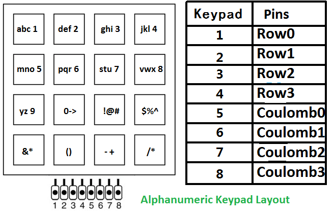
The layout of alphanumeric keypad which i am going to program is below. In first 2 rows each button is assigned 3 characters and 1 number. Next row buttons are mapped to special characters and each button can enter 3 alphabets. Last row is assigned with mathematical operators and up to 2 mathematical operators can be entered by 1 button.
Alphanumeric Keypad Hardware requirements
- 4×4 keypad
- 16×2 lcd
- One 80s51 0r 89c51
- Oscillator to provide necessary clock frequency to micro controller.
- A potentiometer/variable resistor for setting 16×2 lcd contrast.
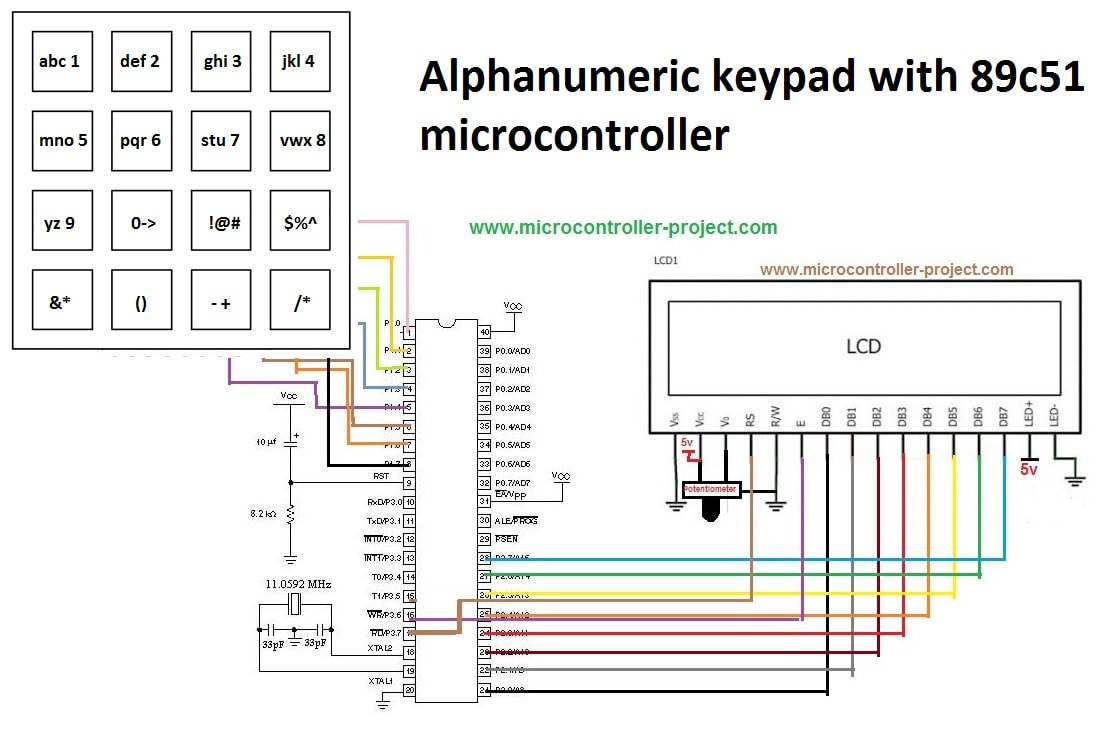
Alphanumeric keypad circuit diagram
Alphanumeric keypad 8051 code
- void keypad() Identifying pressed buttons.
- void cmd(char c) Sending commands to the lcd.
- void delay(int num) Necessary delay function.
- void lcdinit() Initializing the lcd and its driver chip set.
- void lcddata(char c) Sending data to lcd.
The statement sfr dataport=0xA0 is accessing Port-2 of 8051 with its sfr. Then coulomb and row pins are defined on Port-1 of 89c51. 16×2 lcd rw and en(To learn about rw and en click the link) pins are defined at Port-3 pin number 5 and 6.
Next comes my main function starts first with the lcdinit() function. It initializes the lcd 16×2 and its driver chip set. Ten i am printing the string “PLEASE ENTER YOUR NAME ” on my lcd after some time this message disappears and you can enter your name using 4×4 keypad.
Filed Under: 8051, Electronic Projects, Microcontroller Projects

Questions related to this article?
👉Ask and discuss on EDAboard.com and Electro-Tech-Online.com forums.
Tell Us What You Think!!
You must be logged in to post a comment.