Introduction
The world of electronics is all about electrical circuits, electronic components, and interconnected technologies. All these elements can be primarily categorized as digital, analog, or a combination of both. However, here we will be focusing on the basics of the analog category in detail.
Analog electronics is a branch of electronics that deals with a continuously variable signal. It’s widely used in radio and audio equipment along with other applications where signals are derived from analog sensors before being converted into digital signals for subsequent storage and processing. Although digital circuits are considered as a dominant part of today’s technological world, some of the most fundamental components in a digital system are actually analog in nature.
In order to understand the concept, let’s first try to analyze the word ‘Analog’.
What is Analog?
Analog means continuous and real. The world we live in is analog in nature, implying that it’s full of infinite possibilities. The number of smells we can sense, the number of tones we can hear, or the number of colors we can paint with; everything is infinite. The people working in the field of analog electronics are basically dealing with analog devices and circuits.
For example, if we build a circuit and it counts values like 1, 2, 3, 4, and 5; the values are neither infinite nor continuous. On the other hand, if the circuit counts like 1.00000, 1.00001, 1.00002, 4.99999, 5.00000, the amount of information would be infinite.
Analog Signals
Before proceeding with analog signals, let’s understand the simple meaning of a signal. In electrical engineering, signals are basically time-varying quantities (usually voltage or current). So when we talk about the signal it means we are talking about a voltage that’s changing over time.
Signals are passed among devices in order to obtain or send information in the form of audio, video or encoded data. The transmission takes place through wires or via air through radio frequency waves. For instance, audio signals are transferred from the computer’s audio card to the speakers, while data signals between a tablet and a Wi-Fi router pass through the air.
Analog Signals use attributes of the medium to convey the signal’s information. For example, an aneroid barometer makes use of the angular position of a needle to convey the changes in atmospheric pressure. The signals take any value from a given range and each signal value denotes different information. Each level of the signal signifies a different level of the phenomenon and any change in the signal is meaningful.
It’s quite easy to determine if a signal graph is analog or digital. The former one is smooth and continuous while the latter is edge and appears in the form of stepping squares. Given below is an analog signal graph representing the change in voltage with the change in time.
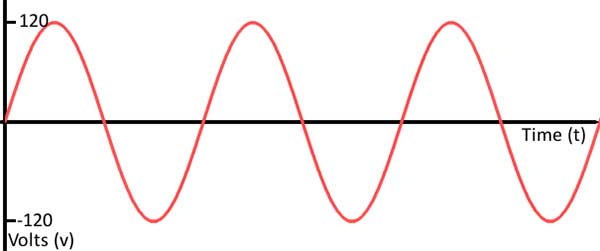
An analog signal graph representing time-voltage graph (Image Courtesy: Sparkfun)
Analog Circuits
Analog circuits can be defined as a complex combination of op amps, resistors, caps, and other basic electronic components. These circuits can be as simple as a combination of two resistors to make a voltage divider or elegantly built with many components. Such circuits can attenuate, amplify, isolate, modify, distort the signal, or even convert the original one into a digital signal.
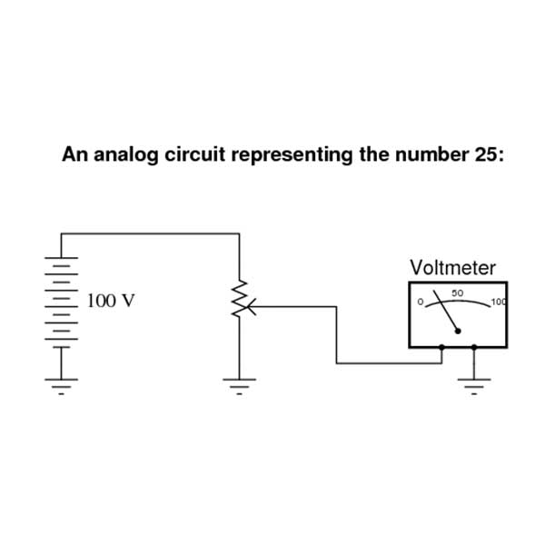
Analog Circuit (Image Courtesy: allaboutcircuits)
These circuits are difficult to design and need a lot of precision as compared to the digital circuits. The modern circuits are rarely found to be completely analog as these days analog circuitry may use digital or microprocessor techniques to improve performance. Such circuits are called mixed signals.
There are two types of analog circuits namely passive and active, where the former ones don’t consume any electrical power while the latter ones do.
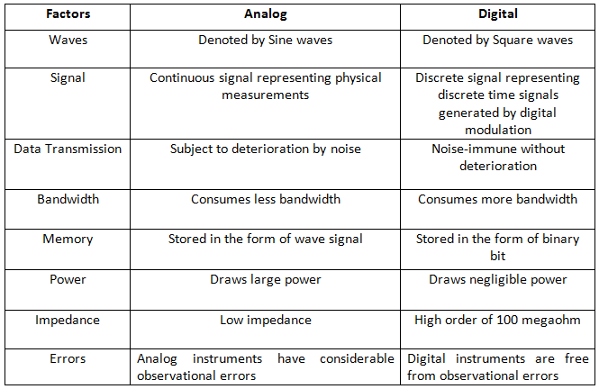
Analog vs Digital Electronics
Analog vs Digital Electronics (Image Courtesy: Sparkfun)
The most basic difference between analog and digital electronics is that in the former technology translates the information into electric pulses of varying amplitude, while the latter translates information into a binary format of 0 and 1, where each bit represents two distinct amplitudes.
However, there are certain characteristic features that clearly state the difference between analog and digital electronics. Let’s have a look at these key aspects:
When to use Analog Components and Circuitry
As mentioned above, analog components are the most basic type of components while the digital components are widely used in today’s devices. Both the branches are independently significant in their own way so we are enlisting certain cases when the analog components and circuitry would be ideal.
Filtering Signals: While dealing with a continuous signal, a continuous analog filter is needed to remove all possible frequency content that you don’t want. As compared to a digital filter, it is much easier to use as well as costs less.
High Power: Although digital measurement and control may be useful for high power systems, a digital signal switching from 0 to 400V may not be efficient enough. The continuous nature of power delivery in the AC and DC systems require analog components as these are more durable and characterized.
Before A/D and After D/A: In order to switch between continuous and discrete data, hybrid systems need both Analog-to-Digital and Digital-to-Analog converters, but as per the Nyquist’s Theorem, the sampling frequency must be at least twice the frequency of the highest frequency component contained in the signal. So, in order to fulfill the theorem, any signal inadvertently included in the original signal can be filtered so as to remove noise after sampling.
Since the signal is not yet digital, the only option is to filter the signal with an analog unit. Once you are done operating on a signal digitally and convert it back to analog, all the processing must once again be done with analog components and circuitry.
Sensors: Sensors convert the real world information into data that can be recognized by a computer or an embedded system. Often the information is not readily available in the real world; rather the sensors first create an analog signal and later convert it into digital signals. Unlike the high voltage systems, sensors have low amplitude and need signal conditioning to increase the value of the signal so as to make a better use of the full range of an ADC.
Filed Under: Tech Articles

Questions related to this article?
👉Ask and discuss on Electro-Tech-Online.com and EDAboard.com forums.
Tell Us What You Think!!
You must be logged in to post a comment.