OBJECTIVE
To design a fully functional and viable Analogue Color Detection system that mirrors the process of color detection and display of a Digital system.
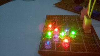
Fig. 1: Image of LED circuit designed on PCB
APPLICATION
When integrated into a small PCB this circuit can be implemented in many systems mainly ranging from showcases to toys.i.e.Chameleon lamp. Future application includes the integration of a small scale Microcontroller and audio ports to create a low cost Blindness Color Speaker or a Real world Color Picker.
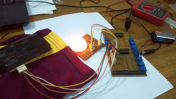
Fig. 2: Prototype of OPAMP based Analog Color Sensor
Also this project can more or less demonstrate most working principles of a practical Op-Amp
DEMONSTRATION
The demonstration of this project is accomplished by mapping the output data to a range of 0-5 Volts and supplying it to an array of Led when are diffused on a Ping-Pong ball.
When light falls on any object it reflects back the color of light that the object represents, White light is comprised of red, blue and green color .Similarly white color is the combination of red blue and green dyes, pertaining to this fact if a light is directed on an unknown color X the light it will reflect back will be the same as its color ,So if we shine a red light individually on the color ,the light it will reflect back will be proportional to the intensity of red color in the object.
We have made a sensor that houses three compartment with isolated the sample from ambient light and shines Red ,Blue and Green colored light individually .It also measures the light intensity response by using an LDR.
Concept Behind Colors
COLOR IS REFLECTED LIGHT
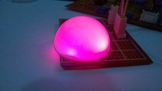
Fig. 3: Representational Image of Color Reflection from Pink LED

Fig. 4: Representational Image of Color Reflection from Blue LED
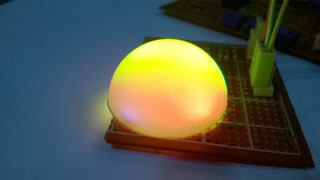
Fig. 5: Representational Image of Color Reflection from Yellow LED
When we see color, we are actually looking at reflected light. When illuminating an object or scene, a light source emits a spectrum of colored wavelengths. For example, sunlight emits a spectrum including infrared, ultraviolet and all visible wavelengths, whereas candlelight emits only red, orange, yellow and infrared wavelengths, giving everything it illuminates an orange cast.
When a scene or object is illuminated, some of the light source’s wavelengths are absorbed and some are reflected. The reflected wavelengths create what we perceive as color. If no light is reflected (or if there is no illumination), the scene or object looks black.
The color of an object depends on two factors – the color of the light source and which wavelengths of light the object reflects. To view the true color of an object, we must illuminate it with a light source that includes all the wavelengths that the object will reflect. For example, if a light source only emits a partial range of wavelengths, an object’s true color may not be visible. For example, if we shine a light source emitting red, green and blue wavelengths at a red strawberry, then the green and blue wavelengths will be absorbed and the red wavelength will be reflected. This means that the strawberry will appear red. However, if only green and blue wavelengths are emitted, they will both be absorbed and the strawberry will appear black.

Fig. 6: Representational image of color perception by human eye
How the eye sees color
Humans can see light with wavelength of between 400nm and 700nm as shown. This range is called visible light. Humans cannot see any light with wavelength above or below this range with special equipment.
When light reflected off an object enters the eye through the pupil it is flipped upside down by a clear lens behind the iris. The light is then projected on to the retina, the part of the eye where vision is generated. The retina contains a lot of vision cells, of two main types – cones and rods. Cone photoreceptors are most important to color vision. The cones distinguish color based on light’s wavelength – for example, a long wavelength is red and a short wavelength is violet. The photoreceptors then convert the wavelengths into electrical signals that are sent to the brain via the nervous system, creating color sight as we know it.
“Color is the visual effect that is caused by the spectral composition of the light emitted, transmitted, or reflected by objects.”
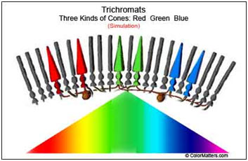
Fig. 7: Image showing perception of color as spectral composition
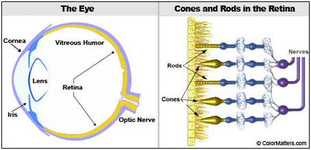
Fig. 8: Diagram showing structure of Human Eye and Retina
Working and Description of Circuit

Fig. 9: Block Diagram of OPAMP based Analog Color Detector
The Above Diagram shows the basic working of the circuit i.e.
1. The RGB Resistive Sensor which consists of 3 LDR and 3 LEDS sensing the light intensity.
2. The voltage divider is connected to the Sensor.
3. The voltage signal form the voltage divider is Isolated and then mapped to be displayed in the display module
In order to simplify the understanding of this circuit the circuit has been divided in to separate modules each of which perform a specified task.
A. Power Supply Module
The power supply module consists of two 9 Volts batteries connected in series to simulate a dual supply for the Op-Amps, a 2.2 Volts Zener Diode used to set the reference voltage in the voltage Subtracter and an LM7805 IC.

Fig. 10: Circuit Diagram of Power Supply
B. Sensing Module
The Sensing module consists of three Light dependent sensors isolated from the ambient light using 1inch white pipes
These sensors consist of a pair of colored led and LDR sensor which is being fed 5 Volts by the Power supply Module.
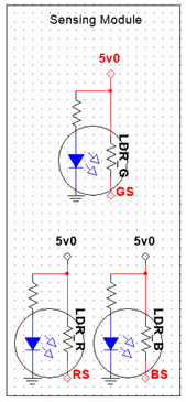
Fig. 11: Circuit Diagram of Sensing Module
C. Voltage Divider Module
The open terminal of the Light Dependent Resistor is connected to it respective voltage divider in the voltage divider module,
The POT value have been set so that all sensors give a minimum of 2.2 volts when they detect black and 3.8+ volts on the max color detection

Fig. 12: Circuit Diagram of Voltage Divider Module
D. Isolation Amplifier Module
The voltage signal from the voltage divider module goes to the Isolation Amplifier Module in order to isolate the signal and fix the problem caused by the resistive sensor i.e. Parallel Connections.
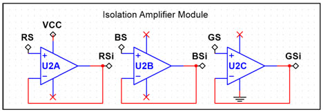
Fig. 13: Circuit Diagram of Isolation Amplifier Module
E. Voltage Mapping Module
The isolated signal from the isolation Amplifier Module is them Mapped from 0 – 5 volts, where 0 V is the output at black and 5 V is the output at maximum voltage.

Fig. 14: Circuit Diagram of Voltage Mapping Module
F. Display Module
The mapped signal from the Voltage Mapping Module is then fed to the Display Modulewhich consists of several LEDS of Red, Blueand Green Colors which are then diffused to display the output color.
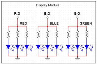
Fig. 15: Circuit Diagram of Display Module

Fig. 16: Image showing circuit diagrams of different sections of Analog Color Detector
Calculations
The value of the voltage divider will be set practically after the implementation of this circuit on the perforated board i.e. to calibrate the device first Place the sensor on a black sample and change the potentiometer value until the voltmeter reads 2.2 Volts On black sample then place the sensor on a white Sample paper and note down the voltmeter values. Repeat this process for all three potentiometer.
Output is calculated by the formula
This equation is derived by using the equation of line method
Where V2 = 2.22 Volts by Zener Diode& V1 = White (VDR) Readings.
The Expected output is for maximum intensity of light is mentioned below

Fig. 17: Table showing light intensity for different colors
CONCLUSION
After many experiments and theories tested, trial & error and error again it can be concluded that even with a significant amount of error in the components used that sensor can detect rudimentary bright colors, the only setback is that sole fact that the display cannot show dark color as the LEDS cannot add the dark element due to ambient light present in the room.
However with further tries, advanced noise cancelation and auto error correction a highly accurate ANALOGUE COLOR SENSOR can be made!!
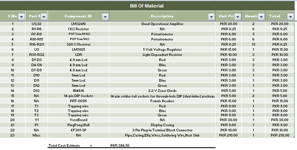
Fig. 18: Screenshot of component list for Analog Color Sensor
Circuit Diagrams
Project Video
Filed Under: Electronic Projects
Filed Under: Electronic Projects


Questions related to this article?
👉Ask and discuss on Electro-Tech-Online.com and EDAboard.com forums.
Tell Us What You Think!!
You must be logged in to post a comment.