I had been working on a project to make a bluetooth controlled car which is being operated from an Android phone. The basic objective of this project is to make a gaming vehicle which would be controlled by tilting the mobile phone such that the user controls its acceleration as well as directions.
The motivation behind my project came basically from the inquisition of Controlling cars using accelerometer in mobile games and PC games. Also we wanted to make such a device which could go into the areas where humans cannot go. Also on seeing many cars used by snake catchers to get the look inside of the snake holes.
I thought this would be a great idea as the remotes use cell batteries which are not available always but one carry his mobile everywhere. My car can be used for surveillance in places where there is no space for humans to enter like at border for the tunnel surveillance, by putting a camera over it. It can also be used for gaming. It can be used by snake catchers to get the insight of the snake holes.This vehicle can also used in areas affected by radiations. Also our vehicle is basic model of a project whose functionality can be doubled. Here are few images of my project:

Fig. 1: Prototype of Arduino and HC-05 Bluetooth Module based Android controlled Robotic Car

Fig. 2: Image showing receiver circuit mounted on Arduino Robot

Fig. 3: Image showing Battery and Arduino circuit mounted on Robotic Car
Description of Circuit
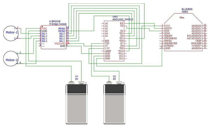
The circuit diagram consists of H-Bridge, an Arduino shield, BluetoothModule connected with batteries and two motors. The connection are given in the circuit diagram (see in tabs) with names of the corresponding pins on the chips.The Vcc and Gnd of the H-Bridge has been connected to the battery(9V), also RX and TX pins in the arduino are connected in TX and RX pins of the Bluetooth chip respectively. The motors are connected with the H-Bridge.We used Amarino app in our android phone to make the transmission.The signals from the amarino are received by the bluetooth which are then sent to the arduino where the processor processes it and according to the code give the instructions to the motor controller to control the motors.
Amarino is a toolkit that enables the rapid prototyping of such applications by connecting the Android operating system to the Arduino microcontroller platform. It consists of an Android application, an Arduino library.This suite of tools allows users to access Android events (ie: compass orientation, accelerometer data, and text messages received) and send them.. If reader is new to used arduino then first read getting start with arduino.
Results:
The final result which my project achieved was quite upto my expectations. I was succesfully able to control the acceleration as well as movements of the car using Android based mobile through Bluetooth

Fig. 4: Image showing Arduino Robot moving by commands passed over Bluetooth interface
Project Source Code
### #include <MeetAndroid.h> MeetAndroid meetAndroid; const int enablepin1 = 5; const int enablepin2 = 10; const int motor1_1 = 3; const int motor1_2 = 4; const int motor2_1 = 8; const int motor2_2 = 9; void setup() { Serial.begin(115200); meetAndroid.registerFunction(phoneorient, 'A'); pinMode(enablepin1, OUTPUT); pinMode(enablepin2, OUTPUT); pinMode(motor1_1, OUTPUT); pinMode(motor1_2, OUTPUT); pinMode(motor2_1, OUTPUT); pinMode(motor2_2, OUTPUT); } void loop() { meetAndroid.receive(); } void phoneorient(byte flag, byte numOfValues) { int values[] = {0, 0, 0}; meetAndroid.getIntValues(values); int steer = values[0]; int turn = values[1]; if(steer >= 10) { steer = 10; } else if(steer <= -10) { steer = -10; } if(turn >= 10) { turn = 10; } else if(turn <= -10) { turn = -10; } int steerpwm = abs(steer) * 25.5; int turnpwm = abs(turn) * 25.5; if((steer <= 10) && (steer > 1)) { analogWrite(enablepin1, steerpwm); analogWrite(enablepin2, steerpwm); digitalWrite(motor1_1, HIGH); digitalWrite(motor1_2, LOW); digitalWrite(motor2_1, HIGH); digitalWrite(motor2_2, LOW); } else if((steer < -1) && (steer >= -10)) { analogWrite(enablepin1, steerpwm); analogWrite(enablepin2, steerpwm); digitalWrite(motor1_1, LOW); digitalWrite(motor1_2, HIGH); digitalWrite(motor2_1, LOW); digitalWrite(motor2_2, HIGH); } if((turn <= 10) && (turn > 1)) {analogWrite(enablepin1, turnpwm); analogWrite(enablepin2, turnpwm); digitalWrite(motor1_1, LOW); digitalWrite(motor1_2, HIGH); digitalWrite(motor2_1, HIGH); digitalWrite(motor2_2, LOW); } else if((turn < -1) && (turn >= -10)) { analogWrite(enablepin1, turnpwm); analogWrite(enablepin2, turnpwm); digitalWrite(motor1_1, HIGH); digitalWrite(motor1_2, LOW); digitalWrite(motor2_1, LOW); digitalWrite(motor2_2, HIGH); } if((steer >= -1) && (steer <= 1) && (turn <= 1) && (turn >= -1)) { analogWrite(enablepin1, LOW); analogWrite(enablepin2, LOW); digitalWrite(motor1_1, LOW); digitalWrite(motor1_2, LOW); digitalWrite(motor2_1, LOW); digitalWrite(motor2_2, LOW); } Serial.println(values[0]); Serial.println(values[1]);} ###
Circuit Diagrams
Filed Under: Electronic Projects

Questions related to this article?
👉Ask and discuss on Electro-Tech-Online.com and EDAboard.com forums.
Tell Us What You Think!!
You must be logged in to post a comment.