The purpose of this projecct is to design and development of an Antenna Tracking System for Airborne vehicles in UHF communication range. It will reduce human involvement and help track automatically the exact position of a system under consideration. It could be an unmanned air vehicle to an unmanned ground vehicle or even a satellite.
![]()
Fig. 1: Image showing field testing of Antenna Tracking System
System Requirements for the Tracking System:
|
Serial No. |
Component |
Specifications |
Requirements |
|
1. |
Directional, 5 Element (433MHz) |
1 |
|
|
2. |
Quadcopter |
3m GPS accuracy, 433MHz transmitter |
1 |
|
3. |
Receiver Module |
433Mhz |
1 |
|
4. |
16 bit, 4K flash memory (or higher) |
1 |
|
|
5. |
150 kg-m (1.8° steps or higher) |
1 |
|
|
6. |
900 kg-m |
1 |
Antenna Design:
• Following are the elements of Yagi-Uda:
– Directors
– Driven Element
– Reflector
• And the following are the parameters of a Yagi-Uda
– The wavelength of the electromagnetic wave, ?
– The length of the driven element
– The length of the directors
– The length of reflector
– Spacing between directors
– Spacing between reflector & driven element
– Spacing between driven element & director
– The type of driven element used
Communication:
|
433 MHz receiver specifications: • Working voltage: 5.0VDC +0.5V • Working current:<=5.5mA max • Working method: OOK/ASK • Working frequency: 433.92MHz • Bandwidth: 2Mhz |
Coaxial cable specifications: • RG-58 • 50 Ohm • Line loss: 9.5 dB/100 ft |
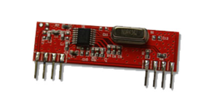
Fig. 2: Typical image of 433 MHz RF Module
Control System Design
• Free body diagram
![]()
Fig. 3: Free Body Diagram of Control System used in Antenna Tracking System
• J1, J2 – moments of inertia
• B1, B2 – coefficients of sliding friction
• T- Torque applied
• O1 – intermediate rotation
• O– Rotational output
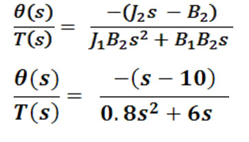
Fig. 4: Image showing calculations used in design of control system
Hardware Control
Servo specifications:
• Voltage: 4.8V – 6V; [5V]
• Speed: 0.16sec/60 deg (4.8v) – 0.18sec/60deg (6v)
• Torque: 9kg.cm (4.8v) – 10kg.cm (6v)
• Size: 40.2mm x 20.1mm x 42.7mm
• Weight: 48g
• Gear Train: metallic
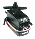
Fig. 5: Typical Image of Servo Motor
Stepper motor (STH – 39D21) specifications:
• Step angle: 1.8°
• Voltage :8 V
• Current : 0.75 A
• Resistance : 19 ?
• Inductance:32 mH
• Control Wires: 4
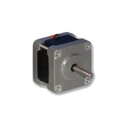
Fig. 6: Typical Image of Stepper Motor
Stepper motor driver (L298N) specifications:
• Supply voltage:upto 46V
• Total DC current:upto 4 amps
• Can connect two unipolar motors simultaneously
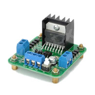
Fig. 7: Typical Image of Power Regulator
Arduino Specifications:
|
Operating Voltage : |
5V |
|
Digital I/O Pins : |
14 |
|
Analog Input Pins : |
6 |
|
Flash Memory : |
32 KB |
|
SRAM : |
2 KB |
|
EEPROM : |
1 KB |
|
Clock Speed : |
16 MHz |
|
Serial Tx and Rx pins: |
present |
|
LED : |
present |
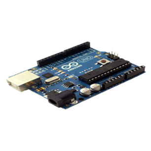
Fig. 8: Typical Image of Arduino Uno
Methodology
• The system is in the ready state initially
• As soon as an airborne system is located in its range of operation, the system starts to receive its GPS coordinates
• On receiving the GPS coordinates, the azimuth and elevation are decoded
• The software module updates the hardware module in accordance with the decoded values
• The antenna, which is controlled by the hardware module, follows the airborne system and collects data from it
• The process repeats till a reset is pressed to stop
Finding Azimuth and Elevation(ECEF: Earth Centered Earth Flat)
• The current azimuth is found using azimuth formula
– The latitudes and longitudes of AURORA are taken as 01 and 01 respectively
– The current values for the airborne system are 02 and 0 2
– f = 1/298.257223563 and 1 – e2 = (1 – f)2

Fig. 9: Image showing Azimuth Formula
• Elevation is found using the linear latitude and longitudes
– If 0 is the latitude in degrees,
– Linear latitude = 111132.954 – 559.822 cos(2 0) + 1.175 cos(4 ?)
– Linear longitude = (p/180)6378137 cos(tan-1 (0.99664719 tan(0 )))
– If x is the latitude and the average radius of the earth is taken into account
– Linear average longitude = (p/180)(6367499) cos(0)
Results
Antenna and its gain pattern
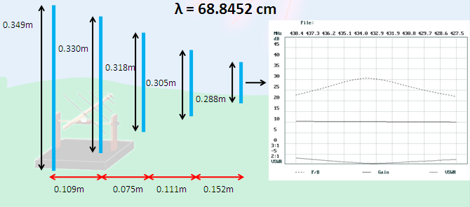
Fig. 10: Graph showing Frequency-Gain Relation for different wavelengths
Radiation patterns:
Elevation (linear
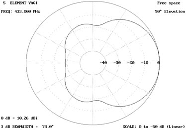
Fig. 11: Image showing linear gain pattern of Antenna at 90 degree elevation
Elevation (log)
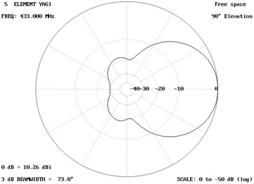
Fig. 12: Image showing log gain pattern of Antenna at 90 degree elevation
Azimuth (linear)
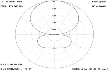
Fig. 13: Image showing linear gain pattern of Antenna at 0 degree azimuth
Azimuth (log)
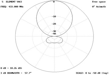
Fig. 14: Image showing log gain pattern of Antenna at 0 degree azimuth
Antenna and Range
Antenna and its range
Height of transmitter (quadcopter) = 10 m
Height of receiver =1 m
|
Antenna Parameter |
Value |
|
Boom Length : |
0.45m |
|
Gain: |
10.32 dB |
|
Diameter of elements : |
0.006 m |
|
Front to Back ratio : |
23.43 dB |
|
Input impedancee: |
51.8 |
|
Directivity: |
9.2dBi |
|
Range Parameter |
Value |
|
|
Radio Line of Sight |
: |
21766.484434 m |
|
Line loses (Due to coax) |
: |
0.31167979002 dB/m |
|
Antenna Gain |
: |
10.26 dB |
|
Path Loss |
: |
46.3781 dBm |
Responses and Stability of System
Step Response
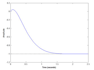
Fig. 15: Graph showing step response of Antenna
Root Locus
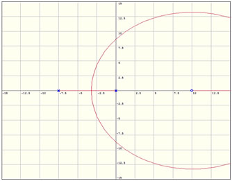
Fig. 16: Graph showing root locus of Antenna
Linear GPS Coordinates and Azimuth at a particular elevation of 56 °

Fig. 17: Table showing Linear GPS Coordinates and Azimuth at a particular elevation of 56 degree
List of azimuths at 50°- 60° elevation range at bus parking lot of RVCE
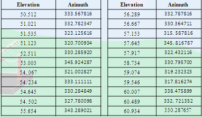
Fig. 18: Table showing List of azimuths at 50°- 60° elevation range at bus parking lot of RVCE
The average azimuth range was found out to be 324.936° This gives the efficiency of 90.26%.
Project Source Code
###


// ------ Code for Elevation


 #include <math.h>

#define DEG_To_RAD 0.0174532925

double deg_lat_base=12.922490;

double deg_lat_tar=12.922608;

double lat,lat_base,lat_tar;

double lon,lon_base,lon_tar;

double rad_lat;

double tar_h=0.005;

double base_h=0.000038;

double rad_long;

void convert(double deg_lat_pass)

{

rad_lat=DEG_TO_RAD*deg_lat_pass;

lat=111132.954-(559.822*cos(2.00*(rad_lat)))+(1.175*cos((4.00*rad_lat)));

rad_long=atan(0.99664719*tan(rad_lat));

lon=DEG_TO_RAD*6378137.00*cos(rad_long);

}

double distance,h;

void dist()

{

distance=((lat_tar-lat_base)*(lat_tar-lat_base))-((lon_tar-lon_base)*(lon_tar-lon_base));

distance=sqrt(fabs(distance));

Serial.println(distance,10);

}

void calc_h()

{

h=(tar_h-base_h);

h=atan(h/distance);

h=h/DEG_TO_RAD;

Serial.println(h,10);

}

void setup()

{

Serial.print(h,9);

}

void loop()

{

Serial.begin(9600);

convert(deg_lat_base);

lat_base=lat;

lon_base=lon;

Serial.println(lat_base,10);

Serial.println(lon_base,10);

convert(deg_lat_tar);

lat_tar=lat;

lon_tar=lon;

Serial.println(lat_tar,10);

Serial.println(lon_tar,10);

dist();

calc_h();

}


// ------- Code for Servo Motor ----


 #include <Servo.h>

Servo myservo; // create servo object to control a servo

// a maximum of eight servo objects can be created

int pos = 0; // variable to store the servo position

void setup()

{

myservo.attach(9); // attaches the servo on pin 9 to the servo object

}

void loop()

{

for(pos = 0; pos < 180; pos += 1) // goes from 0 degrees to 180 degrees

{ // in steps of 1 degree

myservo.write(pos); // tell servo to go to position in variable 'pos'

delay(15); // waits 15ms for the servo to reach the position

}

for(pos = 180; pos>=1; pos-=1) // goes from 180 degrees to 0 degrees

{

myservo.write(pos); // tell servo to go to position in variable 'pos'

delay(15); // waits 15ms for the servo to reach the position

}

}


// ------- Code for Stepper Motor


 int Pin0 = 9; // INP B1

int Pin1 = 10; //INP B2

int Pin2 = 11; // INP A1

int Pin3 = 12; //INP A2

// exchange A1-2 or B1-2 pins if its not working

int _step = 4; // initialize to -1 when dir = true, 4 when dir = false

boolean dir = false;// gre

void setup()

{

pinMode(Pin0, OUTPUT);

pinMode(Pin1, OUTPUT);

pinMode(Pin2, OUTPUT);

pinMode(Pin3, OUTPUT);

pinMode(6,OUTPUT);

pinMode(7,OUTPUT);

digitalWrite(6,HIGH);

digitalWrite(7,HIGH);

}

void loop()

{

if(dir){

_step++;

}else{

_step--;

}

if(_step>3){

_step=0;

}

if(_step<0){

_step=3;

}

switch(_step){

case 0:

digitalWrite(Pin0, HIGH);

digitalWrite(Pin1, LOW);

digitalWrite(Pin2, HIGH);

digitalWrite(Pin3, LOW);

break;

case 1:

digitalWrite(Pin0, LOW);

digitalWrite(Pin1, HIGH);

digitalWrite(Pin2, HIGH);

digitalWrite(Pin3, LOW);

break;

case 2:

digitalWrite(Pin0, LOW);

digitalWrite(Pin1, HIGH);

digitalWrite(Pin2, LOW);

digitalWrite(Pin3, HIGH);

break;

case 3:

digitalWrite(Pin0, HIGH);

digitalWrite(Pin1, LOW);

digitalWrite(Pin2, LOW);

digitalWrite(Pin3, HIGH);

break;

default:

digitalWrite(Pin0, LOW);

digitalWrite(Pin1, LOW);

digitalWrite(Pin2, LOW);

digitalWrite(Pin3, LOW);

break;

}

delay(10);

}###
Circuit Diagrams
Project Video
Filed Under: Electronic Projects
Filed Under: Electronic Projects


Questions related to this article?
👉Ask and discuss on EDAboard.com and Electro-Tech-Online.com forums.
Tell Us What You Think!!
You must be logged in to post a comment.