A lot of Arduino projects involve controlling devices running on DC voltage. The devices running on DC voltage are usually controlled by changing logic at GPIO pins for switching control or by PWM for operational control. There are times when devices running on AC current also needs to be controlled by the microcontroller. For switching control, the AC appliances are usually interfaced to microcontroller boards via relays or relay circuits. For operational control over AC appliances like controlling the speed of a fan or dimming a light bulb, power electronics comes into the picture. This project is a demonstration of operational control of AC appliances using zero voltage crossing detection.
An alternating voltage changes its sign periodically. The alternating voltage supplied to households is usually the sine wave. An alternating voltage can be other forms of the wave also. Irrespective of the waveform, an alternating voltage in the first half of every cycle flows in one direction reaching to a peak voltage and then drops down to zero level. Then in the next half of each cycle, it flows in alternate direction reaching to a peak voltage and then drops down to zero level. The rise and drop of voltage in alternate direction are graphically shown with a negative sign of voltage and voltage curve. The cycles are repeated throughout the voltage supply. For controlling AC appliances operationally, the peak voltage of both the halves of a cycle needs to be chopped off. For this, it is important to detect when voltage alternates its direction. The point on voltage curve where it alternates direction is called zero voltage crossing.
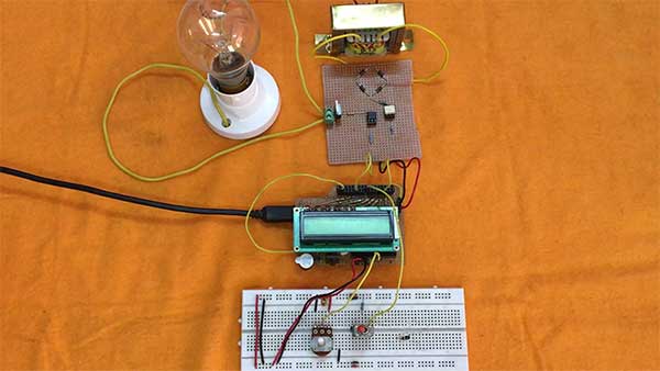
Fig. 1: Prototype of Arduino Based AC Voltage Controller
The zero voltage crossing of AC voltage can be detected by first rectifying it using full wave rectifier and then using an optoisolator which will switch OFF and ON upon zero voltage crossings and past zero voltage crossings respectively. The output of optoisolator can then be passed to the microcontroller to indicate zero voltage crossings to it.
For controlling AC voltage to a load, TRIAC needs to be used. TRIAC (Triode for AC) is commonly used for power control and switching applications. The TRIAC can be feed control using an optocoupler which itself would be driven by a microcontroller pin.
The project is built upon Arduino UNO and 4N25 optoisolator with a full bridge rectifier is used for zero voltage crossing detection. The 3021 optocoupler and BT136 TRIAC are used for chopping off AC voltage to the load. The tasks of zero voltage crossing detection and switching of 3021 IC are programmatically controlled by the Arduino board. The Arduino sketch is written on Arduino IDE and burnt to the board using AVR Dude.
Components Required
• Arduino UNO
• 16×2 LCD
• EL 3021
• 4N25
• ON-OFF Switch
• Voltage regulator -7805
• BT136
• Wire to carry 2A, 230v AC
• 12-0, 1 Amp Transformer
• Two pin plug.
• Bulb holder
• 1N4007 diode
• Terminal block: PBT-2
• 6-pin IC base-2 pieces
• Resistors-10k, 3k3, 330 and 120 ohm
• Bread Board for connection
Block Diagram
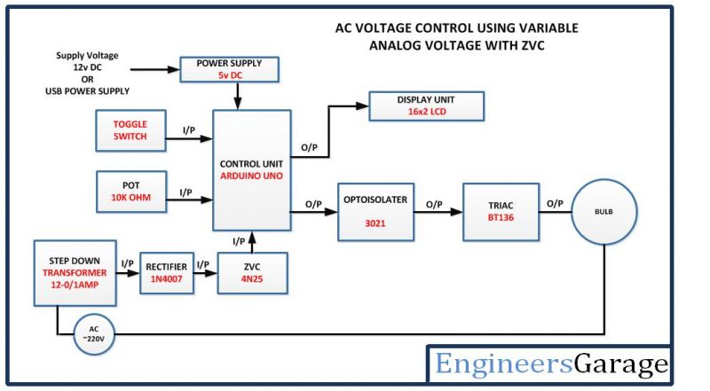
Fig. 2: Block Diagram of Arduino Based AC Voltage Controller
Circuit Connections
The circuit is built around Arduino UNO. There are distinct circuit sections that are interfaced to the Arduino to realize the project functioning. In the project, following circuit sections are assembled together –
Power Supply – The Arduino and LCD module need 5V DC supply. The required DC voltage is supplied by a battery. The supply from the battery is regulated to 5V DC using 7805 IC. The IC has three pins – pin 1 should be connected to the anode of the battery, pin 2 and 3 with the cathode (common ground). The 5V DC should be drawn from the pin 3 of the IC. An LED along with a 10K Ω pull-up resistor can also be connected between common ground and output pin to get a visual hint of supply continuity.
LCD Display – The LCD display is used to show the supplied voltage reading. When the project is powered ON, it first flashes initial messages showing the intent of the project. Once the Arduino sketch initializes the circuit, the voltage supplied to the load is displayed on the LCD screen. The 16X2 LCD display is connected to the Arduino board by connecting its data pins to pins 3 to 6 of the Arduino board. The RS and E pins of the LCD are connected to pins 13 and 12 of the Arduino UNO respectively. The RW pin of the LCD is grounded.

Fig. 3: Table listing circuit connections between Arduino Uno and Character LCD
The standard open-source library for interfacing LCD with Arduino UNO is used in the project. The library works as expected and needs no changes or modifications.
ON-OFF Switch: An ON-OFF switch is provided to turn ON/OFF the supply to the load. The switch is interfaced to Arduino by connecting between ground and pin 7 of the board. The pin 7 by default receives HIGH logic by direct connection to VCC but on toggling the switch it receives a LOW logic. The switching of the supply voltage to the load is controlled by detecting logic at pin 7 of the Arduino board.
Variable Resistor – A 10K ohm resistor is used to change the firing angle. It is connected to the A0 pin of Arduino UNO. The resistance provides an analog voltage which is converted to digital reading by the in-built ADC. The optocoupler 3021 is operated accordingly to control the firing angle.
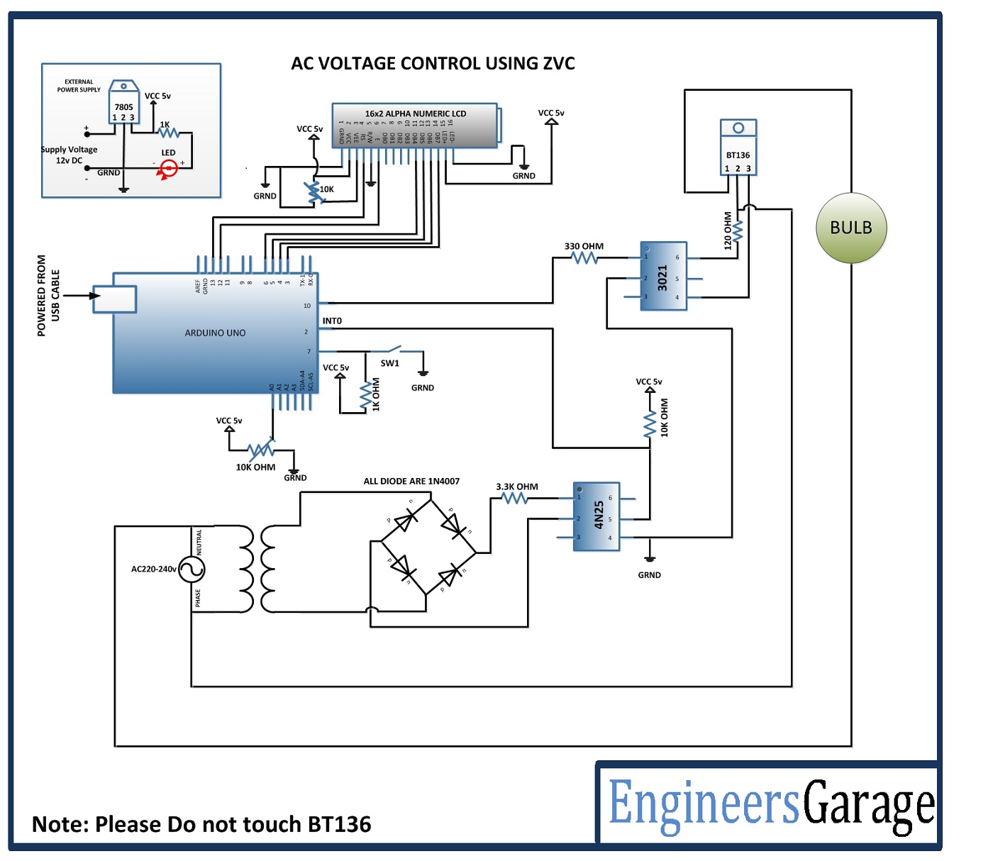
Zero Voltage Crossing Detection Circuit – First the AC voltage from the main supply is stepped down using a transformer to 12V. The stepped down AC voltage is feed to full bridge rectifier circuit built using 1N4007 diodes. The rectified voltage is supplied to pins 1 and 2 of 4N25 optocoupler. The 4N25 is a phototransistor type optocoupler. At pin 1, there is an anode of in-built LED and at pin 2 is the cathode of it. The 4N25 optocoupler has the following pin configuration –

Fig. 4: Table listing pin configuration of 4N25 Opto-Coupler
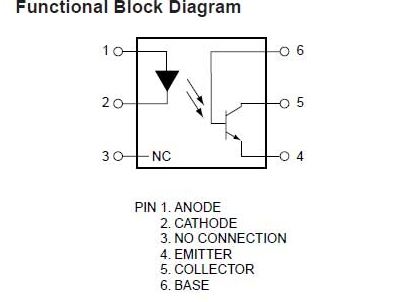
Fig. 5: Pin Diagram of of 4N25 Opto-Coupler
The base of the in-built phototransistor is grounded while the output is drawn from the Collector of the photo-transistor. This way, the photo-transistor actually operates like an LED which gets forward biased when photo-diode glows. The collector pin is connected to pin 2 of the Arduino.
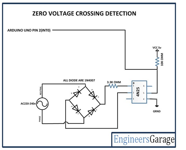
Fig. 6: Circuit Diagram of Zero Voltage Crossing Detector
Opto-Isolator EL3021 – EL3021 is a photo-TRIAC type optocoupler. It should be noted that photo-transistor and photodarlington type optocouplers are used for controlling DC devices while photo-SCR and photo-triac type optocouplers are used for controlling AC devices. The EL3021 has the following pin configuration –

Fig. 7: Table listing pin configuration of EL3021 Opto-Isolator
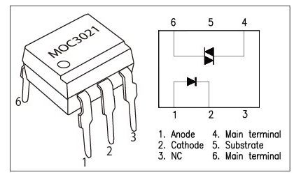
Fig. 8: Pin Diagram of EL3021 Opto-Isolator
The pin 2 of EL3021 is connected to ground and pin 1 is connected to pin 10 of the Arduino. The Main Terminal pins of photo-TRIAC, pins 4 and 6 of EL3021 are connected to pins 3 (Base) and 2 (Main Terminal 2) of BT136. The pin 2 of BT136 and pin 6 of EL3021 are connected to a junction with phase wire of main supplies. The pin 5 of the EL3021 is not connected so the photo-TRIAC actually operates like a photo-DIAC. The load is connected between pin 1 of BT136 and neutral wire. The phase voltage is controlled by the BT136 which itself is controlled by the photo-TRIAC operating as photo-DIAC of EL3021.
TRIAC BT136 – A TRIAC has three terminals – Main Terminal 1, Main Terminal 2 and Gate. TRIAC is equivalent to two SCRs connected in inverse parallel with the gates connected together. Therefore TRIAC works as a bi-directional switch which is triggered by the pulse on the base. The Main Terminal 1 and Main Terminal 2 of the TRIAC are used for connecting phase and neutral wire and the triggering pulse is supplied to Gate terminal from the photo-TRIAC of EL3021. The Gate terminal can be triggered either by a positive or negative voltage. There are four possible modes of the operation of a TRIAC –
a) Main Terminal 2 has a positive voltage compared to Main Terminal 1 and there is positive pulse at Gate
b) Main Terminal 2 has a positive voltage compared to Main Terminal 1 and there is negative pulse at Gate
c) Main Terminal 1 has a positive voltage compared to Main Terminal 2 and there is positive pulse at Gate
d) Main Terminal 1 has a positive voltage compared to Main Terminal 2 and there is negative pulse at Gate
The TRIAC conducts current when either Main Terminal 2 gets a positive voltage with respect to the Main Terminal 1 and the Gate gets a positive trigger or Main Terminal 1 has a positive voltage compared to Main Terminal 2 and there is a negative pulse at Gate. When the Gate current is removed, the TRIAC switches off. BT136 is the TRIAC used in the circuit and has following pin configuration –

Fig. 9: Table listing pin configuration of TRIAC
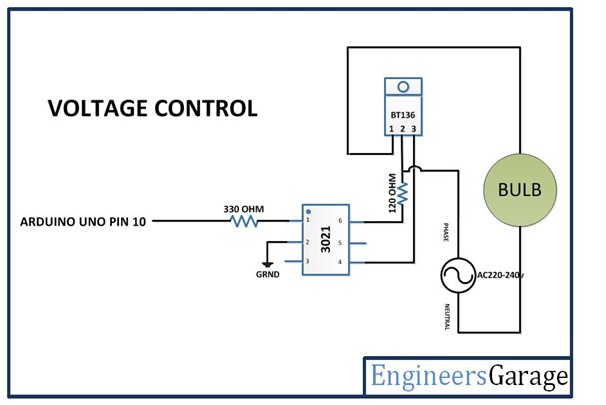
Fig. 10: Circuit Diagram of Voltage Controller
How the Project Works?
The project controls the AC voltage by sending pulses to the Gate pin of BT136 TRIAC. When the circuit is powered ON, the Arduino sketch initializes the circuit and start reading analog voltage supplied through variable resistance at A0 pin. The zero voltage crossing is detected by the 4N25 circuit. The AC voltage from main supplies is stepped down to 12V AC by the transformer and rectified by the 1N4007 diode full-wave rectifier. The AC voltage once converted to DC voltage drives the IR diode of 4N25 forward biasing it for voltage levels greater than 1.1 Volt.
When the voltage level of the rectified wave is above zero voltage crossing, phototransistor of 4N25 remains in forward biased condition, short-circuiting the VCC supply at pin 2 of Arduino to ground. Therefore, for a majority of the waveform, a LOW logic is received at pin 2 of Arduino. When voltage level approaches zero voltage crossing, the IR diode of 4N25 does not get the required voltage for forward biasing. So, the phototransistor of 4N25 switches to unbiased condition and the pin 2 of Arduino get a HIGH pulse upon zero voltage crossing.
The Arduino detects the zero voltage crossing and determines a firing angle based on the voltage supplied through variable resistance at pin A0. The analog voltage at A0 pin is read by the Arduino and converted to a digital reading using in-built ADC channel. A time interval based on digitized voltage reading is calculated in the Arduino Sketch. An interrupt routine shooting a HIGH pulse for 50 microseconds after the delay of the resultant time interval is activated at pin 10 of the Arduino. The HIGH pulse drives the IR diode of an EL3021 optocoupler with the same delay of the calculated time interval. This, in turn, drives the triggering pulse at the Gate terminal of BT136 TRIAC with the same delay equivalent to the calculated time interval.
In power control application using TRIAC, the voltage pulse before the emergence of triggering pulse at Gate terminal of TRIAC gets chopped off while the part of AC voltage wave after the emergence of triggering pulse at Gate terminal of TRIAC remains available for supply to the load.
Check out the Arduino program which is detecting zero voltage crossing based on digital logic at pin 2, calculating a time delay for triggering pulse by digitizing analog voltage through variable resistance at A0 pin and generating a triggering pulse at pin 10 in an interrupt routine.
Programming Guide
First of all, the standard library for LCD needs to be imported. An object of LCD class is declared with pins interfaced to LCD mapped with the object. A constant triacPulse is declared and mapped to pin 10 of the Arduino where the triggering pulse to the Gate terminal of TRIAC has to be generated. Similarly, a variable SW is declared and mapped to pin 7 of Arduino where the toggle switch is connected. A counter variable is declared and initialized to 0.
#include <LiquidCrystal.h>//import the LCD library
LiquidCrystal lcd(13, 12, 6, 5, 4, 3);// Pins used for RS,E,D4,D5,D6,D7
#define triacPulse 10
#define SW 7
int x=0;
A setup() function is called in which the baud rate for serial transmission of data to the LCD is set to 9600 bits per second using Serial.begin() function and the LCD is initialized using lcd.begin() function. The pin 2 where zero voltage crossing is detected by digital logics is configured to digital input using pinMode() function and is pulled up by writing a HIGH logic to it using digitalWrite() function. Similarly, the pin where the triggering pulse is to be generated is set digital output and pin where toggle switch is connected is set digital input. Some initial messages are displayed on the LCD screen showing the intent of the application project.
void setup() {
Serial.begin(9600);
lcd.begin(16,2);//LCD 16×2 initialization
pinMode(2, INPUT);
digitalWrite(2, HIGH); // pull up
pinMode(triacPulse, OUTPUT);
pinMode(SW, INPUT);
digitalWrite(SW, HIGH);
lcd.setCursor(0,0); //Initially set the cursor position of LCD to 1st Columb 1st row.
lcd.print(“Engineers Garage”);//After initialising print data
lcd.setCursor(0,1); //Initially set the cursor position of LCD to 1st Columb 2nd row.
lcd.print(” “); //print blank to clear all the data on LCD
delay(3000);
lcd.setCursor(0,0);
lcd.print(” SPEED CONTROL “);
lcd.setCursor(0,1);
lcd.print(” AC MOTOR “);
delay(3000);
lcd.setCursor(0,1);
lcd.print(” “);
}
The loop function is called where the initial messages are replaced on the LCD and status of the toggle switch is read to proceed the application. If a LOW logic is detected at the pin connected to toggle switch, the Arduino reads analog voltage at pin connecting variable resistance using analogRead() function and calls an interrupt routine. The analog reading is digitized to the proper format and displayed on the LCD screen. If the toggle switch is released and a HIGH logic is detected at the pin, interrupt routine is detached at pin 10 using detachInterrupt() function and a message showing OFF status of supply to the load is displayed on the LCD screen.
void loop() {
lcd.setCursor(0,0);
lcd.print(” AC MOTOR “);
// check for SW closed
if (!digitalRead(SW)) {
x=analogRead(A0);
// enable power
attachInterrupt(0, acon, FALLING);
lcd.setCursor(11,0);
lcd.print(“ON “);
lcd.setCursor(6,1);
lcd.print((analogRead(A0) * 7) + 200);
} // end if
else if (digitalRead(SW)) {
detachInterrupt(0); // disable power
lcd.setCursor(11,0);
lcd.print(“OFF “);
lcd.setCursor(0,1);
lcd.print(” “);
} // else
} // end loop
The interrupt routine in the loop() function calls an acon() function. In the acon() function, a time interval is calculated according to the analog reading at pin A0. The reading digitized to 10-bit value is passed as an argument to delayMicroseconds() function generating a time delay of an equivalent interval. During this interval, a LOW pulse remains on the pin 10 of Arduino. After the calculated delay, a HIGH pulse for 50 microseconds is generated at pin 10 of Arduino.
// begin ac int routine
// delay() will not work!
void acon()
{
delayMicroseconds((analogRead(A0) * 7) + 200); // read AD1
digitalWrite(triacPulse, HIGH);
delayMicroseconds(50);
// delay 50 uSec on output pulse to turn on triac
digitalWrite(triacPulse, LOW);
}
This completes the Arduino sketch for AC voltage control using zero voltage crossing detection.
Project Source Code
###
//Program to #include <LiquidCrystal.h>//import the LCD library LiquidCrystal lcd(13, 12, 6, 5, 4, 3);// Pins used for RS,E,D4,D5,D6,D7 #define triacPulse 10 #define SW 7 int x=0; void setup() { Serial.begin(9600); lcd.begin(16,2);//LCD 16x2 initialization pinMode(2, INPUT); digitalWrite(2, HIGH); // pull up pinMode(triacPulse, OUTPUT); pinMode(SW, INPUT); digitalWrite(SW, HIGH); lcd.setCursor(0,0); //Initially set the cursor position of LCD to 1st Columb 1st row. lcd.print("Engineers Garage");//After initialising print data lcd.setCursor(0,1); //Initially set the cursor position of LCD to 1st Columb 2nd row. lcd.print(" "); //print blank to clear all the data on LCD delay(3000); lcd.setCursor(0,0); lcd.print(" SPEED CONTROL "); lcd.setCursor(0,1); lcd.print(" AC MOTOR "); delay(3000); lcd.setCursor(0,1); lcd.print(" "); } void loop() { lcd.setCursor(0,0); lcd.print(" AC MOTOR "); // check for SW closed if (!digitalRead(SW)) { x=analogRead(A0); // enable power attachInterrupt(0, acon, FALLING); lcd.setCursor(11,0); lcd.print("ON "); lcd.setCursor(6,1); lcd.print((analogRead(A0) * 7) + 200); } // end if else if (digitalRead(SW)) { detachInterrupt(0); // disable power lcd.setCursor(11,0); lcd.print("OFF "); lcd.setCursor(0,1); lcd.print(" "); } // else } // end loop // begin ac int routine // delay() will not work! void acon() { delayMicroseconds((analogRead(A0) * 7) + 200); // read AD1 digitalWrite(triacPulse, HIGH); delayMicroseconds(50); // delay 50 uSec on output pulse to turn on triac digitalWrite(triacPulse, LOW); }###
Circuit Diagrams
Project Video
Filed Under: Electronic Projects
Filed Under: Electronic Projects


Questions related to this article?
👉Ask and discuss on EDAboard.com and Electro-Tech-Online.com forums.
Tell Us What You Think!!
You must be logged in to post a comment.