Air pollution has become a serious issue in the present times. The CO2 level is increasing due to human activities. the effect of pollution is greater in closed spaces like living rooms, cars and offices. This project is developed to detect the level of air pollution and control the pollution level in a restricted area by activating an air purifier as the level exceeds a threshold limit. The system can be installed in houses, offices or cars. The project is developed in an adaptive manner. The device first takes multiple samples of air and determines a threshold level. If the level of CO2 increases the threshold level, the air purifier is activated through a relay circuit.
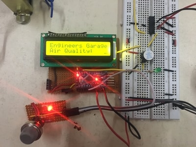
Fig. 1: Prototype of Arduino Based Air Pollution Control System
The project is built on Arduino Pro Mini and MQ-7 gas sensor is used to detect the CO2 levels. The Arduino sketch prompts the system to collect samples, determine a threshold level and activate buzzer and relay circuit operating air purifier whenever pollution level exceeds the limit. The Arduino code is written on Arduino IDE and burnt to the board using AVR Dude.
Components Required –
1. Arduino PRO MINI
2. MQ-7 gas sensor.
3. 16×2 LCD display
4. 7805 voltage regulators
5. 5v Buzzer
6. 5mm LED
7. 1k ohm resistor
8. 12v Relay
Block Diagram –
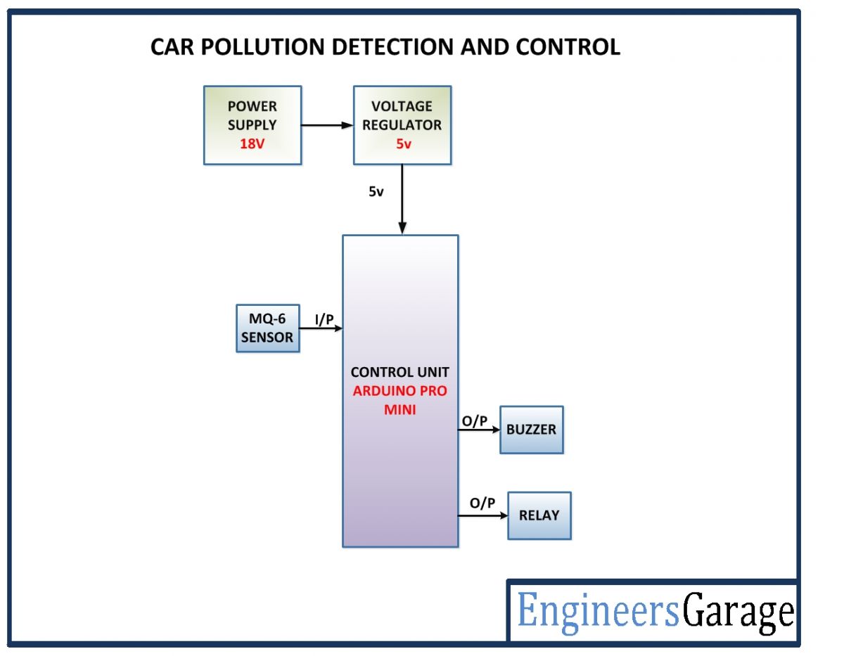
Fig. 2: Block Diagram of Arduino Based Air Pollution Control System
Circuit Connections –
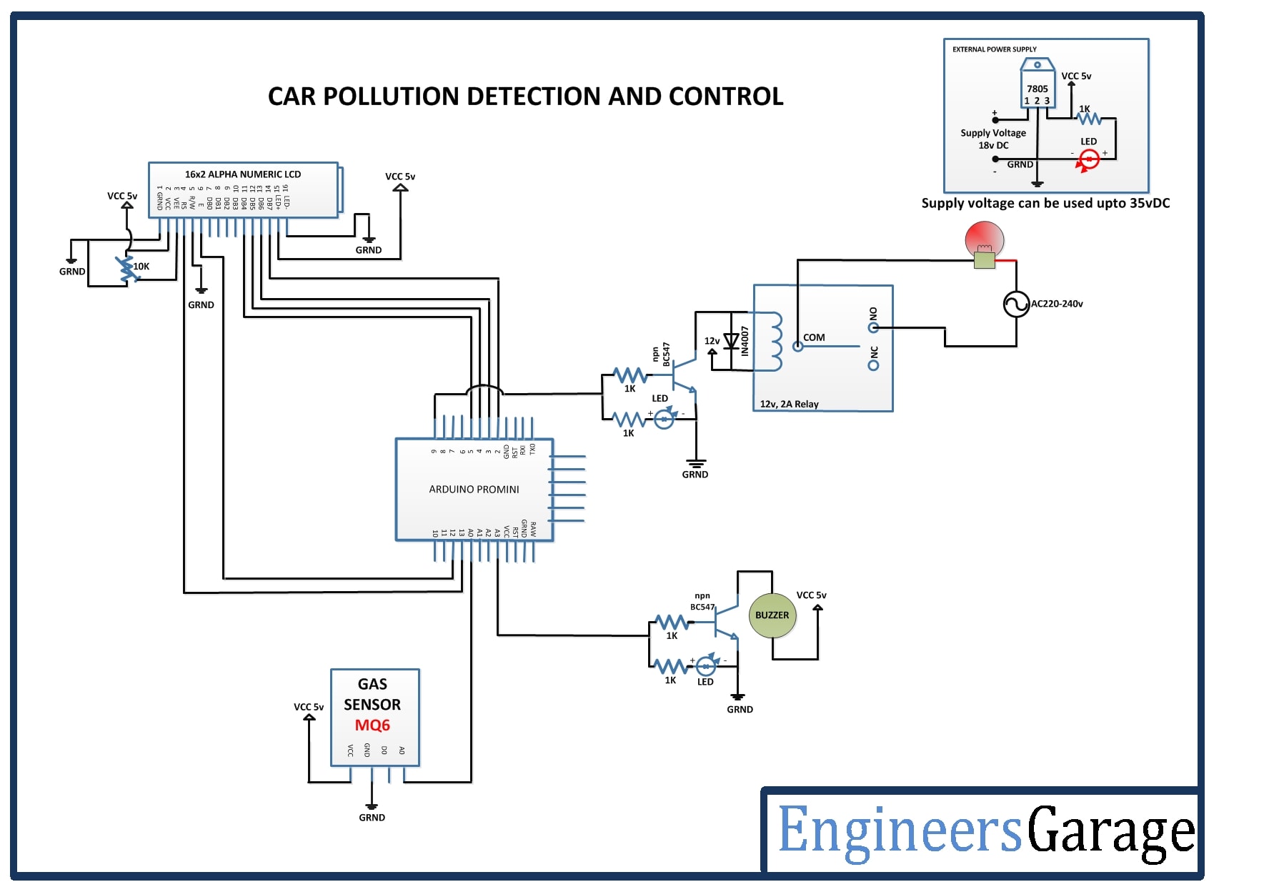
The project is built around Arduino Pro Mini. The following components are interfaced to the Arduino board –
Power supply – The power is provided by an 18V battery. The supply from the battery is regulated to 5V DC using 7805 voltage regulator IC. The IC has three pins – pin 1 should be connected to the anode of the battery, pin 2 and 3 with the cathode (common ground). The 5V DC should be drawn from the pin 3 of the IC. A LED along with a 10K Ω pull-up resistor can also be connected between common ground and output pin to get a visual hint of supply continuity.
Relay Circuit – The relay circuit is used to operate the air purifier. For the project demonstration, a 15 Watt bulb is used instead of actual air purifier circuit. A 12V 2A relay is used to switch the air purifier ON or OFF in the project. The relay is connected to the pin 9 of the Arduino board via BC547 transistor circuit connected in a common emitter configuration. The phase wire from the AC supply is provided at the COM terminal of the relay. When a HIGH logic is received at the interfaced microcontroller pin, the COM point switches from NC to NO point where the relay short-circuits the phase with the neutral wire switching the supply to the air purifier ON. A LED is a connected parallel to the relay circuit with pull-up resistor in series. This LED gives a visual hint of the ON/OFF status of the purifier.
MQ6 Gas Sensor – The MQ6 gas sensor is a gas sensor module. The module has 4 pins for interfacing of which two pins are VCC and ground, one pin is analog output and one pin is digital output pin. The analog output pin of the module is used for detecting concentration level of gas leakage and interfaced with the A0 analog input pin of the Arduino board. The sensor measures the concentration of leaked gas in ppm according to the following formulae –
Concern = 1036.5*R^-2.392 Where
Concern is the concentration of LPG in ppm
R is the ratio of Rs the resistance of sensor to the R0 which is the resistance at 1000ppm at 20 degree Celsius and 65% humidity
The resistance of the sensor Rs is given by the formulae –
Rs = (1024/ADC_DATA-1)*RL where
Rs is the resistance of the sensor
ADC_DATA is digital reading ranging from 0 to 1023
RL is load resistance ranging from 10K to 40K ohms
Therefore, for a fixed load resistance, the ADC reading is proportional to the concentration of gas in ppm.
In the datasheet, the ratio of concentration to the sensor resistance is given. The graph is done under the normal condition of 20 degree Celsius and 65% humidity. And that means Rs=R0 for the curve.
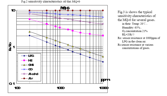
Fig. 3: Graph showing Sensitivity Curve of MQ-6 Sensor
This way the concentration of gas in ppm becomes equal to ADC reading. The ADC reading ranges between 0 and 1023.
16X2 LCD: The 16X2 LCD display is used to display the level of CO2 in air. It is connected to the Arduino board by connecting its data pins to pins 2 to 5 of the Arduino board. The RS and E pins of the LCD are connected to pins 13 and 12 of the Arduino UNO respectively. The RW pin of the LCD is grounded.

Fig. 4: Table listing circuit connections between Character LCD and Arduino Uno
The standard open-source library for interfacing LCD with Arduino board is used in the project. The library works as expected and needs no changes or modifications.
Buzzer – The buzzer is connected to pin A3 of the Arduino board. A common emitter NPN BC547 transistor circuit is used to relay signal from Arduino pin to the buzzer.
How the circuit works –
As the Arduino board is powered on, it loads the required libraries and starts sampling data from the MQ-7 gas sensor. From the collected samples, the Arduino code determines the mean CO2 level of air and set it the threshold level for comparison. The Arduino keeps reading the CO2 level from the gas sensor and if the current CO2 level increases beyond the threshold level, it activates the buzzer and sends a HIGH logic to relay connecting pin switching the air purifier ON. When the CO2 level is again reduced to a permissible level, the Arduino switches OFF the air purifier by sending a LOW logic at the relay connecting pin.
Check out the Arduino sketch to learn how analog data from the gas sensor is sampled, used for determining threshold level, is continuously monitored and compared with determined limit and used to operate relay circuit switching air purifier as required.
Programming Guide –
The Arduino imports the LiquidCrystal library and instantiates an object of LCD type with interfaced Arduino pins mapped to the object. The variables are declared and assigned Arduino pins to represent buzzer, gas sensor and relay from the circuit. The variables to hold CO2 level values and a counter variable are declared. The number of samples is set to 50 declared as variable samples in the code. The pixel maps for custom characters to be displayed on LCD are declared.
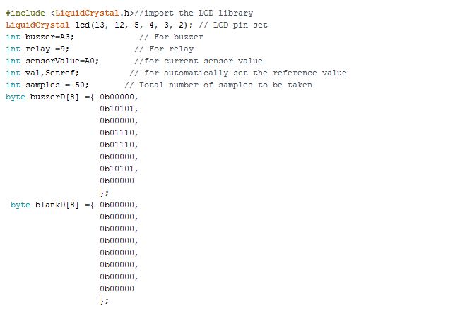
Fig. 5: Screenshot of Initialization in Arduino Code for Air Pollution Control System
The setup() function is called in which the baud rate for serial communication with the LCD module is set to 9600 bits per second and pins connecting relay and buzzer are set to digital output. The LCD is initialized and some initial messages are flashed on it. The samples are read from the gas sensor and a mean value for CO2 level is determined using map() method. The value is saved to Setref variable and displayed on LCD.
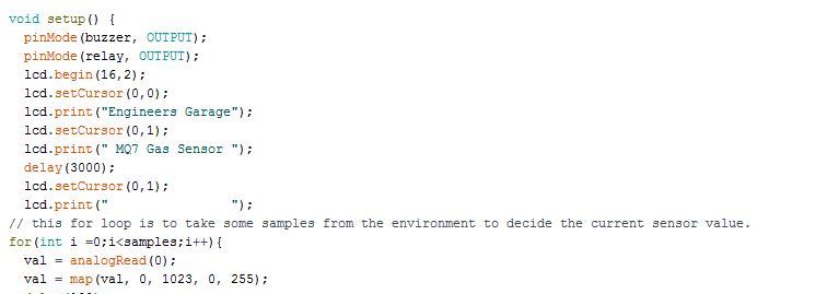
Fig. 6: Screenshot of Setup Function in Arduino Code for Air Pollution Control System
The loop() function is called in which the initial messages are flashed again on LCD and buzzer and relay pin is set to LOW by default. The current value from the sensor is read and compared with a reference value. If it is greater than the reference value, the buzzer is activated and the relay is operated to switch ON the purifier by sending a HIGH logic at the respective pin and alert message is printed on the LCD.
// the loop routine runs over and over again forever:
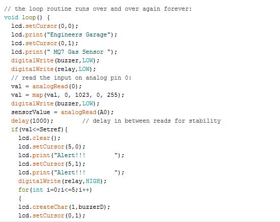
Fig. 7: Screenshot of Loop Function in Arduino Code for Air Pollution Control System
This completes the Arduino sketch for Air Pollution Control Project.
Project Source Code
###
//Program to#include <LiquidCrystal.h>//import the LCD library LiquidCrystal lcd(13, 12, 5, 4, 3, 2); // Sensor sensitivity value set // the setup routine runs once when you press reset: int buzzer=A3; // For buzzer int relay =9; // For relay int count=0; //to count the number of times key pressed int sensorValue=A0; //for current sensor value int val,Setref; // user set sensor value int samples = 50; byte buzzerD[8] ={ 0b00000, 0b10101, 0b00000, 0b01110, 0b01110, 0b00000, 0b10101, 0b00000 }; byte blankD[8] ={ 0b00000, 0b00000, 0b00000, 0b00000, 0b00000, 0b00000, 0b00000, 0b00000 }; void setup() { // initialize serial communication at 9600 bits per second: Serial.begin(9600); pinMode(buzzer, OUTPUT); pinMode(relay, OUTPUT); lcd.begin(16,2); lcd.setCursor(0,0); lcd.print("Engineers Garage"); lcd.setCursor(0,1); lcd.print(" MQ7 Gas Sensor "); delay(3000); lcd.setCursor(0,1); lcd.print(" "); for(int i =0;i<samples;i++){ val = analogRead(0); val = map(val, 0, 1023, 0, 255); delay(100); } Setref=val; Setref= Setref - 20; lcd.setCursor(12,1); printDigits3(Setref); } // the loop routine runs over and over again forever: void loop() { lcd.setCursor(0,0); lcd.print("Engineers Garage"); lcd.setCursor(0,1); lcd.print(" MQ7 Gas Sensor "); digitalWrite(buzzer,LOW); digitalWrite(relay,LOW); // read the input on analog pin 0: val = analogRead(0); val = map(val, 0, 1023, 0, 255); digitalWrite(buzzer,LOW); sensorValue = analogRead(A0); //lcd.setCursor(6,1); Serial.println(val); // printDigits3(val); delay(1000); // delay in between reads for stability if(val<=Setref){ lcd.clear(); lcd.setCursor(5,0); lcd.print("Alert!!! "); lcd.setCursor(5,1); lcd.print("Alert!!! "); digitalWrite(relay,HIGH); for(int i=0;i<=5;i++) { lcd.createChar(1,buzzerD); lcd.setCursor(0,1); lcd.write(1); digitalWrite(buzzer,HIGH); delay(1000); lcd.createChar(2,blankD); lcd.setCursor(0,1); lcd.write(2); digitalWrite(buzzer,LOW); delay(1000); } } } void printDigits3(int digits) //this void function is really useful; it adds a "0" to the beginning of the number, so that 5 minutes is displayed as "00:05:00", rather than "00:5 :00" { if(digits < 100) { lcd.print("0"); lcd.print(digits); } else { lcd.print(digits); } }
###
Circuit Diagrams
Project Video
Filed Under: Electronic Projects
Filed Under: Electronic Projects


Questions related to this article?
👉Ask and discuss on Electro-Tech-Online.com and EDAboard.com forums.
Tell Us What You Think!!
You must be logged in to post a comment.