
Fig. 1: Prototype of Arduino based IOT device for Real Time Air Pollution Monitoring
Components Required –


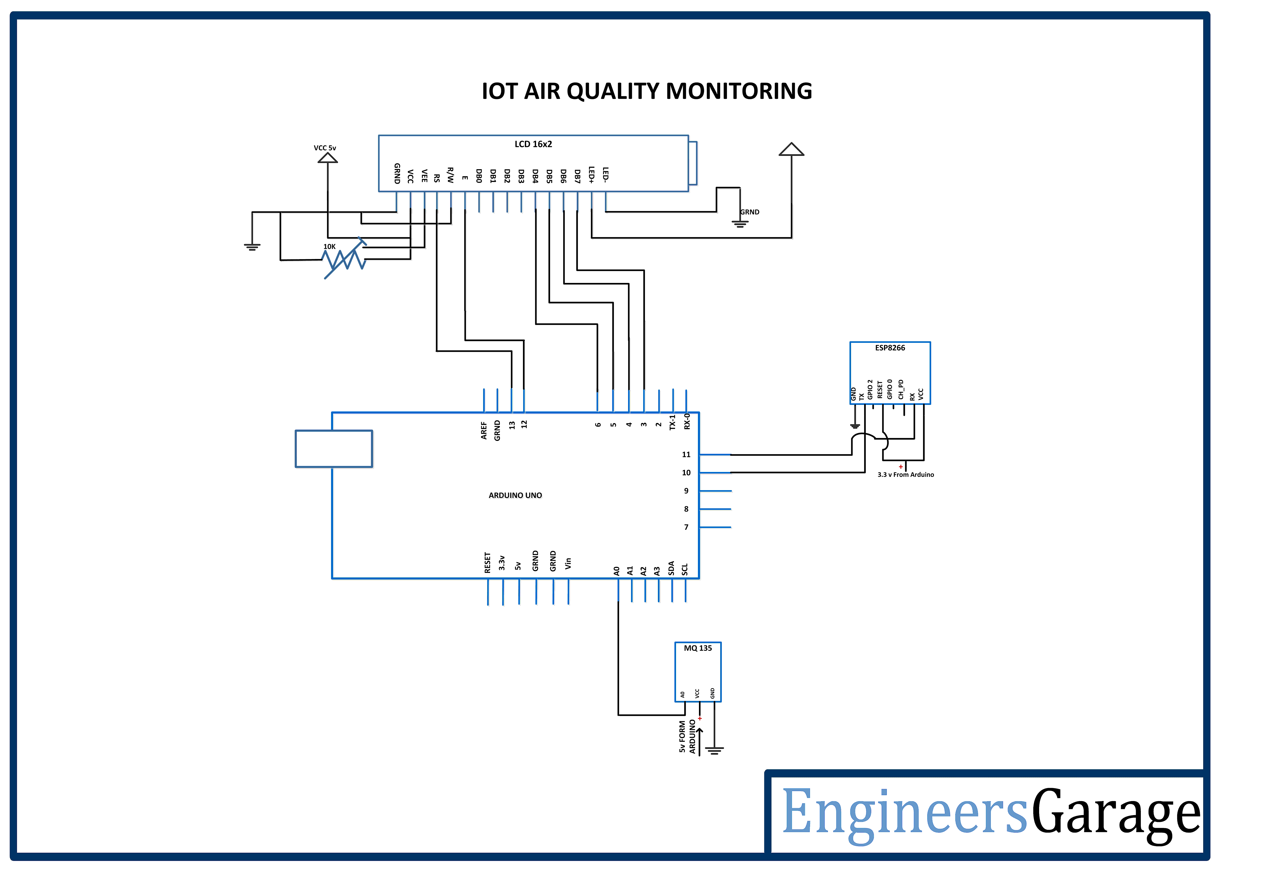
Circuit Connections –
The air pollution monitoring device is built by assembling the following components –


From the sensitivity curve of the sensor, it can be seen that the resistance of the sensor decreases as the concentration of the target gas is increased in PPM while for clean air its resistance remains constant. In the graph, the Rs is the resistance in target gas and Ro is the resistance in clean air. The graph is shown for Carbon dioxide, Carbon Monoxide and Ammonia. The sensitivity of this sensor can be adjusted and calibrated to detect specific concentration level of a target gas. The sensor has four terminals – Ground, VCC, Digital Out and Analog Out. The VCC and Ground terminals of the sensor are connected to the common VCC and Ground. The Analog Output pin of the sensor is connected to the A0 pin of the Arduino. The analog output voltage from the sensor can be assumed directly proportional to the concentration of CO2 gas in PPM under standard conditions. The analog voltage is sensed from the sensor and converted to a digital value in range from 0 to 1023 by the inbuilt ADC channel of the controller. The digitized value is hence equal to the gas concentration in PPM.


 Function in Arduino Code for Real Time IoT Air Pollution Monitor")
 Function in Arduino Code for Real Time IoT Air Pollution Monitor")
 Function in Arduino Code for Real Time IoT Air Pollution Monitor")
Project Source Code
//Program to

#include <SoftwareSerial.h>

#include <LiquidCrystal.h>


LiquidCrystal lcd(13, 12, 6, 5, 4, 3);


float t=0;


char data = 0;


// replace with your channel's thingspeak API key

String apiKey = "8NBNB4VQ9F2EEWQM";


// connect 10 to TX of Serial USB

// connect 11 to RX of serial USB

SoftwareSerial ser(10,11); // RX, TX


// this runs once

void setup()

{

  // enable debug serial

  //Serial.begin(9600);

  // enable software serial

  ser.begin(9600);

  lcd.begin(16, 2);


  lcd.setCursor(0,0);

  lcd.print("Engineers Garage");

  lcd.setCursor(0,1);

  lcd.print("               ");

  delay(3000);


  lcd.clear();

  lcd.setCursor(0,0);

  lcd.print("    IOT AIR");

  lcd.setCursor(0,1);

  lcd.print("QUALITY MONITOR");

  delay(3000);


 // pinMode(12, INPUT);


  // reset ESP8266 WiFi connection AT+CIPMUX=1 AT+CWJAP

  ser.println("AT");

  delay(1000);

  ser.println("AT+GMR");

  delay(1000);

  ser.println("AT+CWMODE=3");

  delay(1000);

  ser.println("AT+RST");

  delay(5000);

  ser.println("AT+CIPMUX=1");

  delay(1000);

  String cmd="AT+CWJAP="EngineersGarage","egP@$$w0rd?"";

  ser.println(cmd);

  delay(1000);

  ser.println("AT+CIFSR");

  delay(1000);


  lcd.clear();

  lcd.setCursor(0,0);

  lcd.print("      WIFI");

  lcd.setCursor(0,1);

  lcd.print("   CONNECTED");

 }


// the loop

void loop()

{

  delay(1000);

  t = analogRead(A0);

  Serial.print("Airquality = ");

  Serial.println(t);


  lcd.clear();

  lcd.setCursor(0,0);

  lcd.print("  SENDING DATA");

  lcd.setCursor(0,1);

  lcd.print("    TO CLOUD");

  esp_8266();


}


void esp_8266()

{

   // TCP connection AT+CIPSTART=4,"TCP","184.106.153.149",80

    String cmd = "AT+CIPSTART=4,"TCP","";

    cmd += "184.106.153.149"; // api.thingspeak.com

    cmd += "",80";

    ser.println(cmd);

    Serial.println(cmd);

    if(ser.find("Error"))

    {

      Serial.println("AT+CIPSTART error");

      return;

    }


  // prepare GET string GET https://api.thingspeak.com/update?api_key=LHAG4NSIYJ5UWS6U&field1=0rnrn

  String getStr = "GET /update?api_key=";

  getStr += apiKey;

  //getStr +="&field1=";

  //getStr +=String(h);

  getStr +="&field1=";

  getStr +=String(t);

  getStr += "rnrn";

  // send data length

  cmd = "AT+CIPSEND=4,";

  cmd += String(getStr.length());

  ser.println(cmd);

  Serial.println(cmd);

  delay(1000);

  ser.print(getStr);

  Serial.println(getStr);


  // thingspeak needs 15 sec delay between updates

  delay(16000);

}

###
Circuit Diagrams
Project Video
Filed Under: Electronic Projects
Filed Under: Electronic Projects

Questions related to this article?
👉Ask and discuss on Electro-Tech-Online.com and EDAboard.com forums.
Tell Us What You Think!!
You must be logged in to post a comment.