Engineers Garage

  • Projects and Tutorials
    • Electronic Projects
      • 8051
      • Arduino
      • ARM
      • AVR
      • PIC
      • Raspberry pi
      • STM32
    • Tutorials
    • Circuit Design
    • Project Videos
    • Components
  • Articles
    • Tech Articles
    • Insight
    • Invention Stories
    • How to
    • What Is
  • News
    • Electronic Products News
    • DIY Reviews
    • Guest Post
  • Forums
    • EDABoard.com
    • Electro-Tech-Online
    • EG Forum Archive
  • Digi-Key Store
    • Cables, Wires
    • Connectors, Interconnect
    • Discrete
    • Electromechanical
    • Embedded Computers
    • Enclosures, Hardware, Office
    • Integrated Circuits (ICs)
    • Isolators
    • LED/Optoelectronics
    • Passive
    • Power, Circuit Protection
    • Programmers
    • RF, Wireless
    • Semiconductors
    • Sensors, Transducers
    • Test Products
    • Tools
  • EE Resources
    • DesignFast
    • LEAP Awards
    • Oscilloscope Product Finder
    • White Papers
    • Webinars
  • EE Learning Center
    • Design Guides
      • WiFi & the IOT Design Guide
      • Microcontrollers Design Guide
      • State of the Art Inductors Design Guide
  • Women in Engineering

Arduino based DC Motor speed controller

By Ashutosh Bhatt

Arduino is a very powerful hardware+software tool for rapid prototype development based on microcontrollers and embedded systems. It is very widely used nowadays for many different embedded applications. It is the first choice for hobbyists, trainers, teachers, students, scientists and even professionals for developing any embedded system application.

For given application of DC motor speed control, the Arduino can be the best choice because the Arduino microcontroller is AVR ATmega328 that has built in 8-bit PWM output that can be used to vary the speed of DC motor. Here in given application, the potentiometer is used to vary DC motor speed. The set speed and motor speed is displayed on LCD and Darlington transistor TIP122 is used to drive DC motor.

Prototype of Arduino based DC Motor Speed Controller

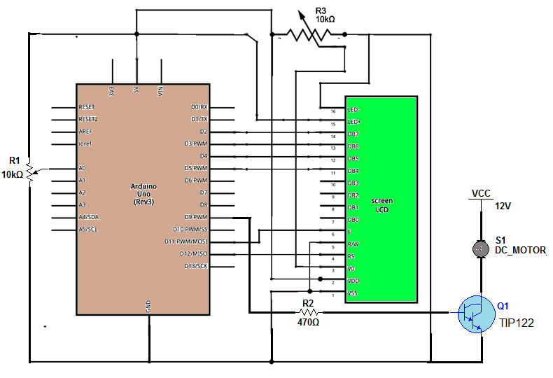
Fig. 1: Prototype of Arduino based DC Motor Speed Controller

The given project very accurately and linearly controls the speed of DC motor from minimum to maximum as the pot is varied from minimum to maximum and it displays set speed and motor speed as 0 – 100 % on LCD.

Circuit description:

1. Data pins D4, D5, D6 and D7 of LCD are connected to Arduino digital pins 5, 4, 3 and 2 respectively. En pin is connected to pin 11 and Rs pin to pin 12. RW pin is connected to ground.

2. A 10K pot is connected to 3rd pin VEE of LCD to vary its brightness. LED+ terminal and LED- terminal are connected to +5 V and ground to turn on LED backlight.

3. Connect pot to an analog input pin A0 as shown. Connect its sliding terminal to A0 and other two terminals to +5 V and ground.

4. Analog output pin 9 is connected to the base input of TIP22 through a current limiting resistor of 470E. The emitter of TIP122 is connected to ground.

5. DC motor is connected between the collector of TIP122 and 12 V external power supply.

Circuit operation:

• As the pot is varied, it will vary analog input voltage to A0 pin. When it is varied from min to max the analog input to pin varies from 0 to 5 V. Arduino will read this analog voltage and convert it into digital value from 0 to 1023.

• This value from 0 to 1023 is displayed as 0 to 100 % of set motor speed on LCD – means if the value is 1023 the set motor speed is displayed as 100% and vice versa.

• This analog input is used to vary the width of the output pulse on analog output pin 9. The pulse width is also varied from 0 to 100% as the pot is varied from min to max.

• As analog input varies from 0 to 1023 the analog output varies from 0 to 255 and it is also displayed on LCD as 0 to 100% of motor speed.

• Because this PWM output is given to DC motor through TIP122, the motor speed increases as pulse width increases and vice versa.

• The PWM output on pin 9 can be observed on CRO/DSO. One can see the increase in pulse width as the pot is turned CW and also observe an increase in speed of the motor. Similarly, as the pot is turned CCW the pulse width will be decreased and so does the speed of the motor.

Software program:

The program does the following tasks -:

• Reads the analog voltage on pin A0 and gives corresponding analog output value from 0 to 1023

• Maps this analog input value from 0 to 1023 into analog output from 0 to 255 to vary pulse width on pin 

• Displays set speed and motor speed as 0 to 100% on LCD.

The program is edited and compiled in Arduino IDE software. Then it is uploaded into Arduino board microcontroller ATMega328.

Project Source Code

###

//Program to 

#include <LiquidCrystal.h>

LiquidCrystal lcd(12, 11, 5, 4, 3, 2);

#define potpin A0

#define motor_pin 9

int set_speed,motor_speed,disp_speed;
void setup() 

{

   lcd.begin(16, 2); // initialize LCD as 16x2

   lcd.setCursor(0,0); // display message in 1st and 2nd line

   lcd.print("Set speed: ");

   lcd.setCursor(0,1);

   lcd.print("MotorSpeed:");

}
void loop()

{

    int set_speed = analogRead(potpin); // take input from pot

    lcd.setCursor(12,0);

    lcd.print(set_speed/10); // display set speed in %

    lcd.print('%');

    motor_speed = set_speed/4; // set motor speed as PWM width

    analogWrite(motor_pin,motor_speed);

    disp_speed = (motor_speed*100)/255; // display motor speed(PWM width) in %

    lcd.setCursor(12,1);

    lcd.print(disp_speed);

    lcd.print('%');

    delay(200); // delay for 0.2 sec

 }

###


Circuit Diagrams

Circuit-Diagram-Arduino-Based-DC-Motor-Speed-Controller

Project Video


Filed Under: Electronic Projects


Questions related to this article?
👉Ask and discuss on Electro-Tech-Online.com and EDAboard.com forums.


Tell Us What You Think!! Cancel reply

You must be logged in to post a comment.

HAVE A QUESTION?

Have a technical question about an article or other engineering questions? Check out our engineering forums EDABoard.com and Electro-Tech-Online.com where you can get those questions asked and answered by your peers!


Featured Tutorials

  • Introduction to Brain Waves & its Types (Part 1/13)
  • Understanding NeuroSky EEG Chip in Detail (Part 2/13)
  • Performing Experiments with Brainwaves (Part 3/13)
  • Amplification of EEG Signal and Interfacing with Arduino (Part 4/13)
  • Controlling Led brightness using Meditation and attention level (Part 5/13)
  • Control Motor’s Speed using Meditation and Attention Level of Brain (Part 6/13)

Stay Up To Date

Newsletter Signup

Sign up and receive our weekly newsletter for latest Tech articles, Electronics Projects, Tutorial series and other insightful tech content.

EE Training Center Classrooms

EE Classrooms

Recent Articles

  • What are the battery-selection criteria for low-power design?
  • Key factors to optimize power consumption in an embedded device
  • EdgeLock A5000 Secure Authenticator
  • How to interface a DS18B20 temperature sensor with MicroPython’s Onewire driver
  • Introduction to Brain Waves & its Types (Part 1/13)

Most Popular

5G 555 timer circuit 8051 ai Arduino atmega16 automotive avr bluetooth dc motor display Electronic Part Electronic Parts Fujitsu ic infineontechnologies integratedcircuit Intel IoT ir lcd led maximintegratedproducts microchip microchiptechnology Microchip Technology microcontroller microcontrollers mosfet motor powermanagement Raspberry Pi remote renesaselectronics renesaselectronicscorporation Research samsung semiconductor sensor software STMicroelectronics switch Technology vishayintertechnology wireless

RSS EDABOARD.com Discussions

  • ADS error message: Internal timestep 1.91586e-10 too small at time 5.00000e-10
  • Pull up via GPIO
  • Timer MC14541B wrong delay
  • Band Pass Filte
  • Horizontally flipping the boardin Allegro

RSS Electro-Tech-Online.com Discussions

  • Best way to reduce voltage in higher wattage system?
  • Turn CD4029 on/off with TTP223
  • Need a ducted soldering fan for solder smoke extraction
  • Power failure relay options
  • DIY bluetooth speaker
Engineers Garage
  • Analog IC TIps
  • Connector Tips
  • DesignFast
  • EDABoard Forums
  • EE World Online
  • Electro-Tech-Online Forums
  • Microcontroller Tips
  • Power Electronic Tips
  • Sensor Tips
  • Test and Measurement Tips
  • 5G Technology World
  • About Us
  • Contact Us
  • Advertise

Copyright © 2022 WTWH Media LLC. All Rights Reserved. The material on this site may not be reproduced, distributed, transmitted, cached or otherwise used, except with the prior written permission of WTWH Media
Privacy Policy | Advertising | About Us

Search Engineers Garage

  • Projects and Tutorials
    • Electronic Projects
      • 8051
      • Arduino
      • ARM
      • AVR
      • PIC
      • Raspberry pi
      • STM32
    • Tutorials
    • Circuit Design
    • Project Videos
    • Components
  • Articles
    • Tech Articles
    • Insight
    • Invention Stories
    • How to
    • What Is
  • News
    • Electronic Products News
    • DIY Reviews
    • Guest Post
  • Forums
    • EDABoard.com
    • Electro-Tech-Online
    • EG Forum Archive
  • Digi-Key Store
    • Cables, Wires
    • Connectors, Interconnect
    • Discrete
    • Electromechanical
    • Embedded Computers
    • Enclosures, Hardware, Office
    • Integrated Circuits (ICs)
    • Isolators
    • LED/Optoelectronics
    • Passive
    • Power, Circuit Protection
    • Programmers
    • RF, Wireless
    • Semiconductors
    • Sensors, Transducers
    • Test Products
    • Tools
  • EE Resources
    • DesignFast
    • LEAP Awards
    • Oscilloscope Product Finder
    • White Papers
    • Webinars
  • EE Learning Center
    • Design Guides
      • WiFi & the IOT Design Guide
      • Microcontrollers Design Guide
      • State of the Art Inductors Design Guide
  • Women in Engineering