Gardening is a common hobby for nature lovers. The plants need continuous and closely monitored care. Sometimes, this turn into a liability. Like when the care taker of a home garden needs to go out of station for a while, the garden may remain unattended for some time or even long time. The Internet of Things can offer a feasible solution to this. The garden can be modernized with electronic technology that continuously monitors the conditions of plants and soil, so the plants could be provided watering and shade as required. All of this can be controlled and monitored online with the application of IoT.
In this project, a simple garden monitoring system based on Internet of Things is designed. An IoT device built on Arduino UNO and equipped with sensors like DHT-11 Temperature and Humidity sensor, Moisture sensor and LDR sensor is designed which sends environmental data to ThingSpeak IoT platform by connecting to a Wi-Fi Access Point. The ESP8266 Wi-Fi modem is interfaced to the Arduino to connect with a Wi-Fi hotspot. The device is also interfaced with a water pump controlled by L293D motor driver IC. The water pump is automatically controlled based on the values of the various environmental factors. The various environmental factors like temperature, humidity, soil moisture and light intensity can be monitored on the Freeboard.io dashboard.
In fact many such devices can be installed to keep a watch in a large garden. The Arduino Sketch running over the device implements the various functionalities of the project like reading sensor data, converting them into strings, passing them to the IoT platform, receiving commands from the IoT platform to control water pump and controlling water pump for timely watering of plants. The Sketch is written, compiled and loaded using the ArduinoIDE. The IoT platform used is ThingSpeak and the Freeboard.io is used to built the IoT Dashboard.

Fig. 1: Prototype of Arduino based IoT Garden Monitoring System
Components Required –

Fig. 2: List of Components required for Arduino based IoT Garden Monitoring System
Block Diagram –

Fig. 3: Block Diagram of Arduino based IoT Garden Monitoring System
Circuit Connections –
The garden monitoring device is built on Arduino UNO.So reader should have knowledge of How to start with Arduino. The Arduino UNO is one of the most popular prototyping board that is commonly used even in the IoT projects. Various sensors like DHT-11, Moisture sensor and LDR, the ESP8266 Wi-Fi Modem and L293D motor driver IC are interfaced to the Arduino.

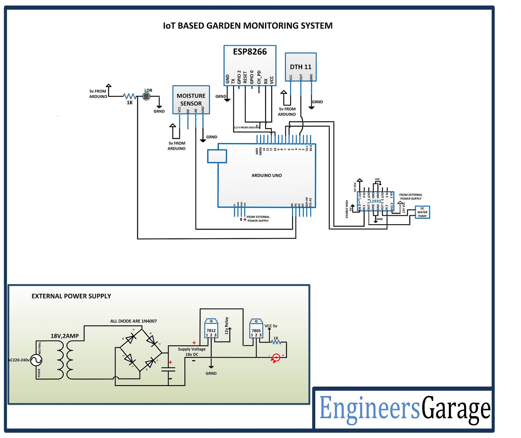
Fig. 4: Image showing Circuit Connections of Arduino based IoT Garden Monitoring System
The Arduino based IoT device has the following circuit connections –
Arduino UNO – The Arduino UNO is ATmega328 based microcontroller board. It is one of the most popular prototyping boards. The board comes with built-in arduino boot loader. It has 14 GPIO pins, 6 PWM pins, 6 Analog inputs and on board UART, SPI and TWI interfaces, an on-board resonator, a reset button, and holes for mounting pin headers. While programming the board, it can be connected to the PC using USB port and the board can runs on USB power. The Arduino UNO has 32 Kb Flash memory, 1 Kb EEPROM and 2 Kb SRAM. The board can be connected to different Arduino Shields for connectivity with Ethernet, Bluetooth, Wi-Fi, Zigbee or Cellular network and it can be connected to most of the IoT platforms. The ATmega328 controller has the following pin configuration –

Fig. 5: Table Listing Pin Configuration of Arduino Uno
In this project, the two Analog Input pins of the board are used to interface the LDR and Moisture sensor, one GPIO is used to interface DHT-11 sensor, two GPIO are used to interface ESP8266 module where pins are configured UART transmitter and receiver pins using software serial and 2 GPIO pins are used to interface the L293D motor driver IC.
DHT-11 Sensor – DHT-11 is a temperature and humidity sensor. The DHT11 sensor consists of two main components – one is Humidity sensing component and other is NTC temperature sensor (or Thermistor). The Thermistor is actually a variable resistor that changes its resistance with change in temperature. They both sense the temperature and humidity of area and give the output to the IC (which is placed on back side of sensor). The sensor has four pins – VCC, Ground, data Out and NC. The VCC and Ground pins are connected to the common VCC and Ground respectively. The Data Out pin of the sensor is connected to Pin 3 of the Arduino board.
LDR Sensor – The LDR is used to sense the intensity of light. The sensor is connected to the A1 pin of the Arduino board. The sensor is connected in a potential divider circuit. The LDR provides an analog voltage which is converted to digital reading by the in-built ADC.
Moisture Sensor – An Arduino compatible soil moisture sensor is used in the project. The sensor measures the volumetric water content of the soil with the help of a sensing probe which must be put into the soil. The sensor module operates between a voltage of 3.3 V to 5V. It has a LM393 comparator on-board. The module has four terminals – VCC, Ground, Data out and Analog output. The VCC and Ground pins are connected to the common VCC and Ground respectively. The Analog Output pin of the sensor is connected to A0 Pin of the Arduino board.
ESP8266 Module – The ESP8266 Wi-Fi Module is a self contained SOC with integrated TCP/IP protocol stack that can access to a Wi-Fi network. The ESP8266 is capable of either hosting an application or off loading all Wi-Fi networking functions from another application processor. Each ESP8266 module comes pre-programmed with an AT command set firmware. The module comes available in two models – ESP-01 and ESP-12. ESP-12 has 16 pins available for interfacing while ESP-01 has only 8 pins available for use. The ESP-12 has the following pin configuration –

Fig. 6: Table Listing Pin Configuration of ESP8266 ESP-12 Modem
The ESP-01 model is used in the project. The ESP-01 model has the following pin configuration –

Fig. 7: Table Listing Pin Configuration of ESP8266 ESP-01 Modem
The RESET and VCC pins of the module are connected to the 3.3 V DC while Ground pin is connected to the common ground. The Tx and Rx pins of the module are connected to the 10 and 11 pins of the Arduino UNO.
L293D DC Motor Driver IC – The L293D is the motor control driver IC. It has 16 pins with following pin configuration:

Fig. 8: Table listing Pin Configuration of L293D Motor Driver IC
A water pump is controlled in the circuit using L293D which is connected between pins 3 and 6 of the IC.
The L293D IC controls any DC Motors according to the following truth tables:

Fig. 9: Truth Table of L293D Motor Driver IC
The pins 2 and 7 of the L293D are connected to pins 6 and 7 of the Arduino board and let control the rotation of the pump. The pin 1 and 16 (VSS) are connected to 5V DC and pin 8 (VS) is connected to 12V DC supply. The pins 4 and 5 are grounded. The pins 12 and 13 of the motor driver IC are also grounded.
Power Supply – The circuit requires 5V DC for its operation while the motor driver IC also needs 12V DC. The AC mains is used as the primary source of power. The supply from the mains is stepped down by a transformer and rectified by a full-bridge rectifier. The rectified output is regulated to 5V and 12V using 7805 and 7812 ICs. The pin 1 of both the voltage regulator ICs is connected to the anode of the battery and pin 2 of both ICs is connected to ground. The respective voltage outputs are drawn from pin 3 of the respective voltage regulator ICs. An LED along with a 10K Ω pull-up resistor is also connected between common ground and output pin to get a visual hint of supply continuity.
How the circuit works –
This Arduino based IoT device can be installed anywhere in a garden. Once it is properly installed and powered on, it connects with the internet via Wi-Fi modem and start reading data from the interfaced sensors – DHT-11 temperature and humidity sensor, Moisture Sensor and the LDR sensor.
DHT11 Temperature and Humidity Sensor is a digital sensor with inbuilt capacitive humidity sensor and Thermistor. It relays a real-time temperature and humidity reading every 2 seconds. The sensor operates on 3.5 to 5.5 V supply and can read temperature between 0° C and 50° C and relative humidity between 20% and 95%.
The sensor cannot be directly interfaced to a digital pin of the board as it operates on 1-wire protocol which must be implemented only on the firmware. First the data pin is configured to input and a start signal is sent to it. The start signal comprises of a LOW for 18 milliseconds followed by a HIGH for 20 to 40 microseconds followed by a LOW again for 80 microseconds and a HIGH for 80 microseconds. After sending the start signal, the pin is configured to digital output and 40-bit data comprising of the temperature and humidity reading is latched out. Of the 5-byte data, the first two bytes are integer and decimal part of reading for relative humidity respectively, third and fourth bytes are integer and decimal part of reading for temperature and last one is checksum byte.
For Arduino, standard library for DHT-11 sensor is already available. The data from the sensor can be easily ready by calling read11() method of the DHT class.
The LDR sensor is connected in a potential divider circuit and inputs a voltage at the analog input pin of the controller. The voltage is read and digitized using in-built ADC channel.
The moisture sensor also has an analog output which is sensed at A0 pin of the Arduino UNO and is converted to a calibrated value using in-built ADC. The moisture sensor outputs an analog voltage in range from 0 to 4.2 V. The Arduino has 10-bit ADC channel, so the detected voltage is converted to a value in range from 0 to 1024. The drier is the soil the higher is the voltage output of the sensor. The moisture can be expressed in percentage by calibrating the voltage output of the sensor in dry and wet soil.
The Arduino collects data from all the sensors and convert the values to the strings. The ESP8266 Wi-Fi module connected to the Arduino uploads the data to ThingSpeak Server. For displaying and monitoring data uploaded to the ThingSpeak server, either a digital dashboard or data broker is needed. In this project, a digital dashboard called Freeboard.io is used to monitor the sensor data visually online. The Freeboard.io use JASON file to visualize ThingSpeak data. It offers three elements to build a dashboard –
1) Data Sources – The data sources get the data from external sources. These external sources can be data broker services, JavaScript applications or JSON files receiving content from an HTTP server. In this project, the data source is a JSON file that receives data from the ThingSpeak server.
2) Widgets – The Widgets help to display data in textual or graphical form. There are many widgets available in Freeboard.io like text, graph, gauge etc.
3) Panes – These are used to organize widgets.
Freeboard.io requires sign up and after sign widgets can be created.

Fig. 10: Screenshot of Freeboard Sign Up Page
Freeboard.io Sign Up
There are four gauge type widgets created to monitor temperature, humidity, light intensity and soil moisture.
The dashboard on Freeboard.io can be created as follow –
1. Go to freeboard.io website and sign up with a new account.
2. Enter the name and click on the create button, after entering into the new window, click on the create data source and select type as JASON.

Fig. 11: Screenshot of Gauge Type Widgets on Freeboard API
Freeboard.io Data Source Selection
3. After that fill the fields to indicate the IoT platform. In the URL tab, change the number 392797 with the respective channel id.
4. After creating the data source, click on add pane and select as Gauge.

Fig. 12: Screenshot of Creating Data source on Freeboard API
Freeboard.io Widget Creation
5. At the pane, after selecting the Gauge select the following as shown below and create the widgets.

Fig. 13: Screenshot of Making Data Source Selection on Freeboard API
Freeboard.io Gauge Widget Creation
This way the sensor data can be uploaded on ThingSpeak server and viewed online at Freeboard.io dashboard. The dashboard can be accessed from any device like Smart Phone, Laptop or PC having an Internet connectivity.
The water pump is automatically controlled depending upon the values of the environmental factors detected by the Arduino. If the moisture level is below 80%, the pump is switched ON and keeps running until the moisture level is retained.
The Arduino board needs to connect with a Wi-Fi access point in order to connect with the internet. The name and password of the Wi-Fi access point are hard-coded in the Arduino sketch. The initialization of the Wi-Fi connection is done within the setup() function of the Arduino Sketch which runs once the board is powered on.
The setup of Wi-Fi connection is run by passing AT commands to the ESP8266 Wi-Fi modem. The modem is connected to GPIO pins of the Arduino which are configured as UART transmitter and receiver pins by using software serial library. The Wi-Fi is initialized by passing the following AT commands to ESP module –
AT : This command is passed to check if modem is functioning properly.
AT+GMR: This command is passed to print the firmware version.
AT+CWMODE=3 : This command is passed to set the Wi-Fi mode to both AP as well as Station mode.
AT+RST: This command is passed to reset the modem.
After reset, the modem check IP addresses of the available access points. The ESP modem can connect with the access point whose SSID and Password are hard-coded in the Arduino Sketch. The following AT command is passed to connect with the Access Point –
AT+CWJAP
Once the modem is connected to an access point, it obtains IP address by executing the following command –
AT+CIFSR: This command is used to obtain IP address of ESP module as an client.
The IP address is stored in a string and acknowledged to the Arduino board. Once the sensor data is collected, the following AT commands are passed to the ESP module for sending it to the cloud-
AT+CIPSTART=4,”TCP”,”184.106.153.149″,80: This command is passed to start a TCP connection with the given IP address at the specified port (80).
AT+CIPSEND=4, String(getStr.length()): This command is passed to send data at the previously mentioned IP address with the number of transmit connections set to 4 and length of data (which can be maximum 2048 bytes) specified.
So, the Arduino connects with the server via ESP modem and the sent data can be graphically observed on Freeboard.io.
Programming Guide –
The Arduino sketch manages to collect data from the DHT-11, Moisture sensor and LDR sensor, convert sensor values to string, control water pump via L293D IC and pass data to the ThingSpeak server. First the standard open-source library of Arduino for interfacing DHT11 is imported and software Serial library for serial communication with the Wi-Fi module is imported. The variables representing pin connections to read the sensor data are initialized.

Fig. 14: Screenshot of Initialization of Arduino Code for IoT Garden Monitoring System
Initialization in Arduino Sketch for IoT Garden Monitoring System
The setup() function is called in which baud rate for the serial communication for communication with the Wi-Fi modem is set to 9600. The Wi-Fi mode and network connectivity is established using the AT commands with some delays. The delay should be given according to time it takes to connect with the network.

Fig. 15: Screenshot of Setup Function in Arduino Code for IoT Garden Monitoring System
Setup Function in Arduino Sketch for IoT Garden Monitoring
The loop() function is called in which the sensor data is fetched and stored in the initialized variables. The water pump is controlled by passing appropriate digital logic at the input pins of the L293D motor driver IC. The esp8266() function is called for transmitting data to the cloud.

Fig. 16: Screenshot of Loop Function in Arduino Code for IoT Garden Monitoring System
Loop Function in Arduino Sketch for IoT Garden Monitoring System
At the esp8266() function, the AT commands for establishing TCP connection are passed, and then API key of the ThingSpeak is given to transmit a data to the registered channel. At every 16 seconds, the data gets updated to the ThingSpeak channel.

Fig. 17: Screenshot of Function Managing IoT communication in Arduino Sketch for IoT Garden Monitoring System
Function Managing IoT communication in Arduino Sketch for IoT Garden Monitoring System
This completes the Arduino sketch for IOT Based Garden Monitoring System. Check out the Arduino Sketch from the code section to try it out.
This Project is easy to built and can be installed anywhere in a garden. It allows automatic maintenance of the garden and remote monitoring with the help of IoT.
You may also like:


Project Source Code
###
//Program to /*=========================================================================*/ /*Standard Library */ /*=========================================================================*/ #include#include /*=========================================================================*/ /*Variable Initialization for Senor pins */ /*=========================================================================*/ dht DHT; #define DHT11_PIN 3 #define RM_1 6 #define RM_2 7 float t=0; float h=0; int sen_val = 0; int lig_val = 0; char data = 0; #define MOS_SEN A0 #define LDR_SEN A1 /*=========================================================================*/ /*API key for thingspeak and change with your API */ /*=========================================================================*/ String apiKey = "CAM10KIK7YH2HAO0"; /*=========================================================================*/ /*Serial pins for connecting WiFi module */ /*=========================================================================*/ SoftwareSerial ser(10,11); // RX, TX /*=========================================================================*/ /*Setup() function that runs first */ /*=========================================================================*/ void setup() { Serial.begin(9600); pinMode(MOS_SEN, INPUT); pinMode(LDR_SEN, INPUT); pinMode(RM_1, OUTPUT); pinMode(RM_2, OUTPUT); ser.begin(9600); // reset ESP8266 WiFi connection AT+CIPMUX=1 AT+CWJAP /*========================================================================*/ /*AT commands for establishing WiFi connection */ /*========================================================================*/ ser.println("AT"); delay(1000); ser.println("AT+GMR"); delay(1000); ser.println("AT+CWMODE=3"); delay(1000); ser.println("AT+RST"); delay(5000); ser.println("AT+CIPMUX=1"); delay(1000); String cmd="AT+CWJAP="EngineersGarage","egP@$$w0rd?""; ser.println(cmd); delay(1000); ser.println("AT+CIFSR"); delay(1000); } /*========================================================================*/ /*Loop functions that runs infinitely that collects sensor data */ /*========================================================================*/ void loop() { delay(1000); int chk = DHT.read11(DHT11_PIN); Serial.print("Temperature = "); t = DHT.temperature; Serial.println(t); Serial.print("Humidity = "); h = DHT.humidity; Serial.println(h); lig_val = analogRead(LDR_SEN); int mos_val = read_mos(); if(mos_val > 80) { Serial.println("Start"); digitalWrite(RM_1, HIGH); digitalWrite(RM_2, LOW); } else if(read_mos() < 80) { Serial.println("Stop"); digitalWrite(RM_1, LOW); digitalWrite(RM_2, LOW); } Serial.println(sen_val); delay(500); Serial.print("Light Intensity = "); Serial.println(lig_val); delay(500); esp_8266(); } /*========================================================================*/ /*esp8266 funtion that uploads data to web */ /*========================================================================*/ void esp_8266() { // TCP connection AT+CIPSTART=4,"TCP","184.106.153.149",80 String cmd = "AT+CIPSTART=4,"TCP",""; cmd += "184.106.153.149"; // api.thingspeak.com cmd += "",80"; ser.println(cmd); Serial.println(cmd); if(ser.find("Error")) { Serial.println("AT+CIPSTART error"); return; } // prepare GET string GET https://api.thingspeak.com/update?api_key=LHAG4NSIYJ5UWS6U&field1=0rnrn String getStr = "GET /update?api_key="; getStr += apiKey; getStr +="&field1="; getStr +=String(h); getStr +="&field2="; getStr +=String(t); getStr +="&field3="; getStr +=String(sen_val); getStr +="&field4="; getStr +=String(lig_val); getStr += "rnrn"; // send data length cmd = "AT+CIPSEND=4,"; cmd += String(getStr.length()); ser.println(cmd); Serial.println(cmd); delay(1000); ser.print(getStr); Serial.println(getStr); //thingspeak needs 15 sec delay between updates delay(15000); } int read_mos() { sen_val = analogRead(MOS_SEN); Serial.print("Moisture = "); sen_val = map(sen_val,0,1023,0,255); return sen_val; } ###
Circuit Diagrams
Project Video
Filed Under: Electronic Projects
Filed Under: Electronic Projects

Questions related to this article?
👉Ask and discuss on EDAboard.com and Electro-Tech-Online.com forums.
Tell Us What You Think!!
You must be logged in to post a comment.