A maze solving robot is designed to move in a maze and escape through it by following its walls. A maze solving robot is quite similar to a line follower. Like a line follower has to follow black strip lines, a maze follower finds a wall and starts following it until it finds an escape route. But unlike a line follower which has just to follow a predetermined route, a maze follower is designed to find an escape route that is not known beforehand. However, both types of robots are designed to be autonomous, they basically perform different tasks.
The maze solving robot designed in this tutorial is built on Arduino UNO and has the maze solving algorithm implemented within the Arduino Sketch. The hardware design of the robot is quite similar that of any other typical line follower robot except that a line follower may have sensors only in the front side of the robot, the maze solving robot has sensors at left side, right side and front side of the robot. The electronic circuitry of the robot consists of the Arduino board, IR sensor array and L293D motor driver IC coupled with two geared DC motors. The robot is powered by a 12V battery and is programmed to instantly start finding an escape route once it is powered by the battery.
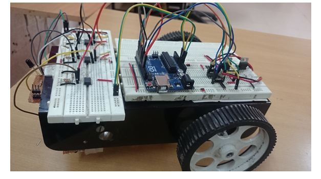
Fig. 1: Prototype of Arduino based Maze Solving Robot
Components Required –
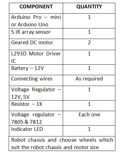
Fig. 2: List of components required for Arduino based Maze Solving Robot
The following components will be required for designing the sensor array –
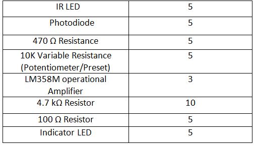
Fig. 3: List of components required for IR Sensor Module
Block Diagram –
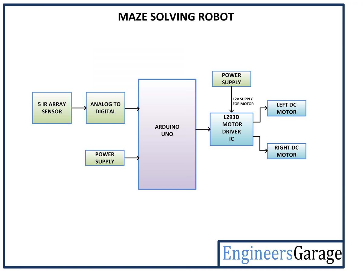
Fig. 4: Block Diagram of Arduino based Maze Solving Robot
Circuit Connections –
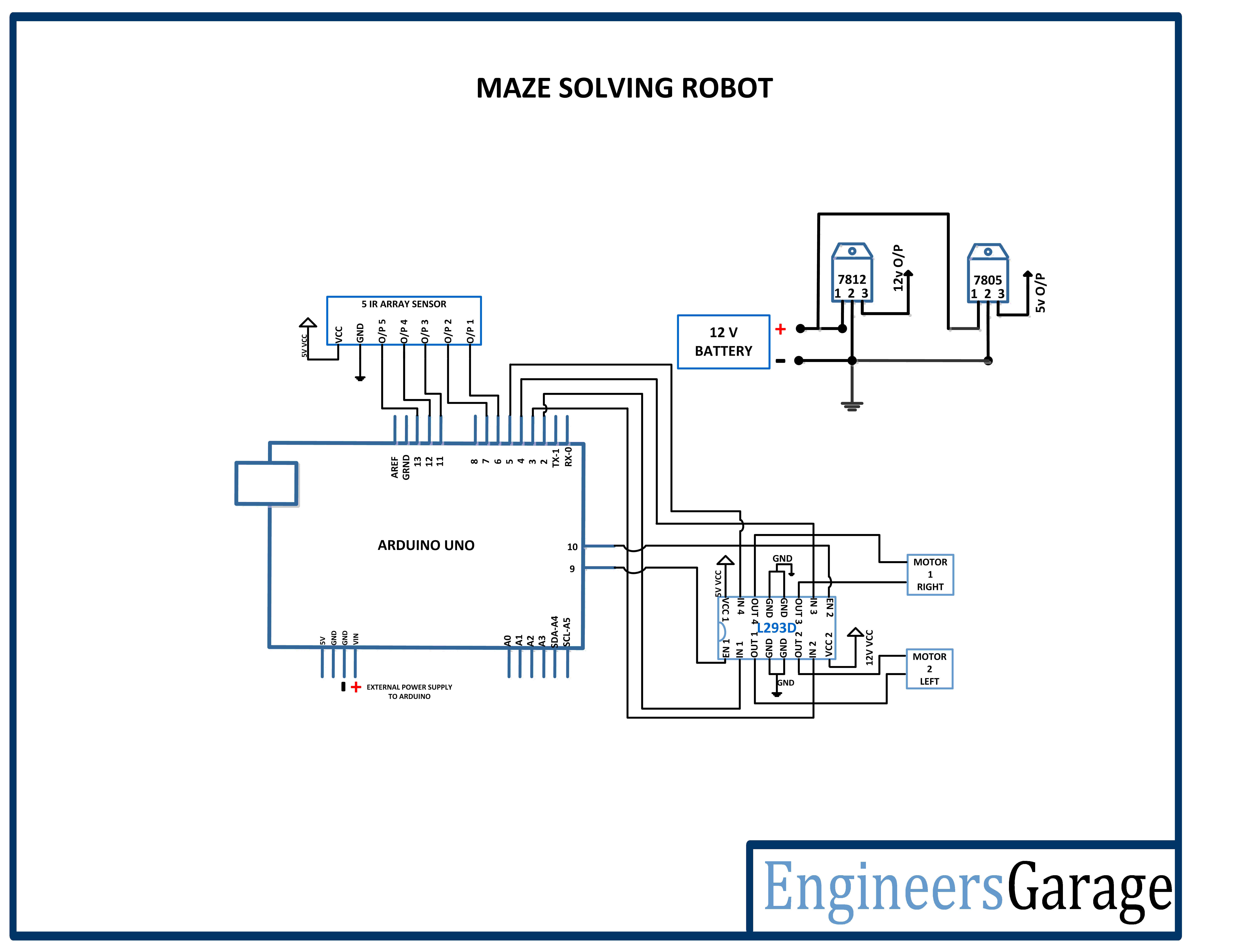
The maze solving robot has to find an escape route by following walls of the maze. For that, it is equipped with an IR sensor array and a motor driver circuit. Both the sensor circuit as well the motor driver circuit are interfaced with the Arduino board. The electronic circuit controlling the robot has the following building blocks –
Power Supply – In the circuit, Arduino board and IR sensor array need a 5V regulated DC for their operation while the motor driver IC needs 12V DC. A 12V NIMH battery is used as the primary source of power. The supply from the battery is regulated to 5V and 12V using 7805 and 7812 ICs. The pin 1 of both the voltage regulator ICs is connected to the anode of the battery and pin 2 of both ICs is connected to ground. The respective voltage outputs are drawn from pin 3 of the respective voltage regulator ICs. An LED along with a 10K Ω pull-up resistor is also connected between common ground and output pin to get a visual hint of supply continuity. Despite using 12V battery, 7812 is used to provide a regulated and stable supply to the motor driver IC. The DC motors cannot be directly connected to the battery as they can only be controlled by the motor driver IC and the motor driver IC itself need a regulated power input.
Arduino UNO – Arduino UNO is one of the most popular prototyping boards. It is used frequently in robotic applications as it is small in size and packed with rich features. The board comes with built-in Arduino boot loader. It is an Atmega 328 based controller board which has 14 GPIO pins, 6 PWM pins, 6 Analog inputs and on board UART, SPI and TWI interfaces. In this project, 5 GPIO pins of the board are utilized to connect the IR sensors and 6 GPIO pins are used to interface L293D motor driver IC.
L293D DC Motor Driver IC – The L293D is a dual H-bridge motor driver integrated circuit (IC). The Motor drivers act as current amplifiers since they take a low-current control signal and provide a higher-current signal. This higher current signal is used to drive the motors. It has 16 pins with following pin configuration –
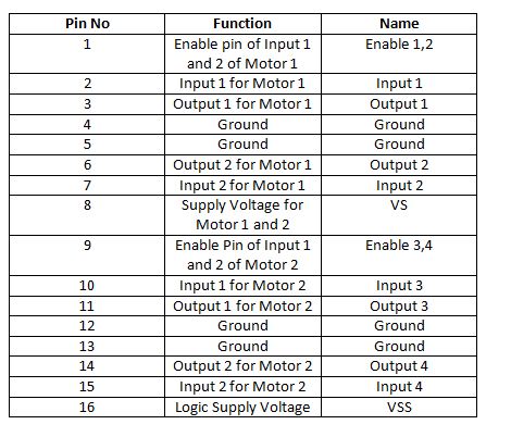
Fig. 5: Table listing pin configuration of L293D Motor Driver IC
For robot’s motion, there are two DC motors used. The DC motors are interfaced between pins 3 and 6 and pins 14 and 11 of one of the motor driver IC.
The L293D IC controls the DC Motors according to the following truth tables:
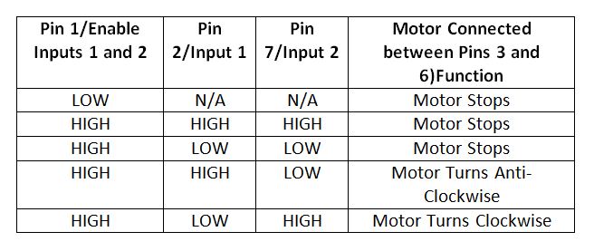
Fig. 6: Truth Table of L293D Motor Driver IC
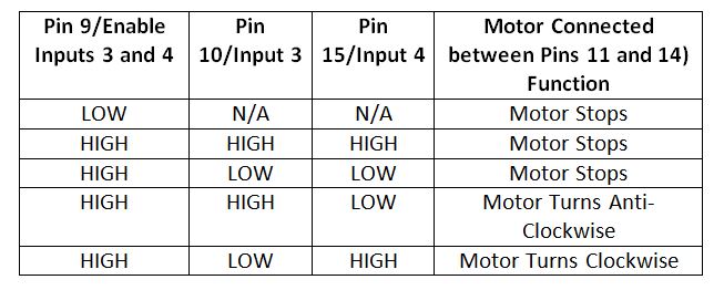
Fig. 7: Truth Table of L293D Motor Driver IC
The pin 4, 5, 13 and 12 of the L293D IC are grounded while pins 1, 16 and 9 are connected to 5V DC and pin 8 is connected to 12V DC. The pins 15, 2, 7 and 10 of this motor driver IC are connected to pins 5, 2, 3 and 4 of the Arduino board. The DC motor attached to right wheel is connected to pins 11 and 14 while motor attached to left wheel is connected to pins 3 and 6 of the motor driver IC. The pins 15, 2, 7 and 10 are input signal pins of the motor driver IC. These are connected to Arduino pins. On changing digital logic at the Arduino pins, the logic at the input pins of the motor driver IC is also changed. As summarized in the tables above, the direction of rotation of the DC motors depends upon the digital logic at the input pins of the motor driver IC. The pins 1 and 9 of the IC are connected with the pins 9 and 10 of the Arduino board. These are enable pins for the DC motors.
Geared DC Motors – In this robot, 12V geared DC motors are attached to the wheels. Geared DC motors are available with wide range of RPM and Torque, which allow a robot to move based on the control signal it receives from the motor driver IC.
IR sensor array – The maze solving robot is designed to follow walls of the robot and turn in the direction where it finds no walls. For this, a sensor which can detect the side walls is required. The IR sensors can detect the walls of the maze based on reflective/non-reflective indirect incidence. The IR LEDs emit IR radiation which in normal state gets reflected back from the white surface of the wall but can be absorbed by a black spot or surface.
The reflected radiations are detected by the photodiodes. Assuming walls to be of white colour, the IR radiations will be reflected back from the wall. But when there will be no wall, the radiations will not be reflected back. This way, an IR sensor module can detect the presence of side walls and obstacles in front of the robot. The IR sensors are available with analog output as well as digital output. In this robot, the sensor module is designed using the IR sensors having digital output.
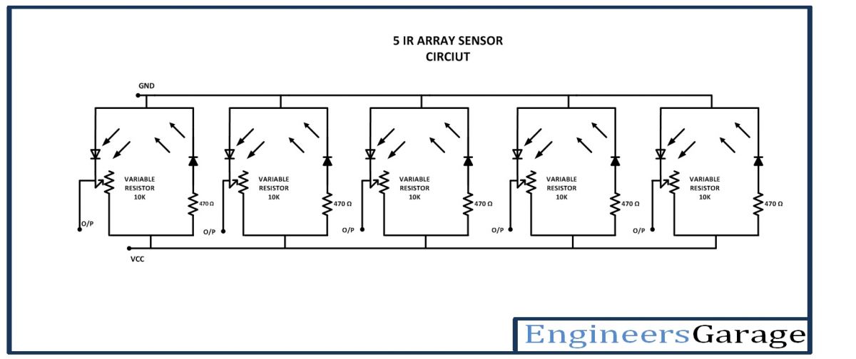
Fig. 8: Circuit Diagram of IR Sensor Array
The IR sensor modules are constructed by the following components –
a) IR Transmitters – The IR LEDs are used as IR transmitters in the circuit. An IR LED is a type of LED which emits light in the Infra-Red frequency range. The infra-red radiations are not visible to the human eye but can be seen by the lenses of a camera. Operationally, IR LEDs are not much different from normal LEDs. They also need a 3V DC for biasing and consume 20 mA current. They also need to be connected with pull-up resistor in a circuit. In the module, IR LEDs are connected with 470 ohm pull-up resistors.
b) IR Receivers – The photodiodes are used as IR receivers in the circuit. A photodiode is a type of diode which gets forward biased when light is incident on it. It has a high resistance when no light is falling on it. When the intensity of light incident on it increases, it starts getting forward biased and current starts flowing through it. So, when light is incident on it, its resistance decreases and there is less voltage drop across it. When light is not incident on it, its resistance increases and there is higher voltage drop across it. The photodiode looks exactly like an LED and may have a dark blue or black film on the outer casing. The photodiodes are used in reverse bias configuration in the circuit.
Variable resistor – The variable resistors are used in the sensor circuit to form a resistive voltage divider. The VCC is applied at the variable resistor side, so the output from the voltage divider is proportional to the resistance of the variable resistor and is inversely proportional to the resistance of the respective photodiode. The use of variable resistor allows calibrating the sensor circuit to properly detect the walls of the maze.
LM358M OPAM – The LM358M is used to add operational amplifiers in the circuit. The LM358M is a general purpose Dual Operational Amplifier (Op-Amp). The OPAM are used as negative voltage comparators in the circuit. The LM358M is an 8-pin IC with following pin configuration –
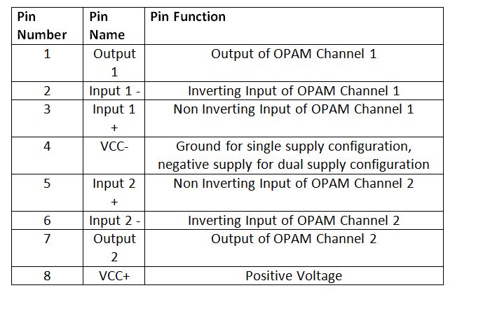
Fig. 9: Table listing pin configuration of LM358M OPAM IC
The IC is used in single supply configuration in the circuit. For five IR sensor modules, three LM358M ICs are used as each IC provides two OPAM circuits. Any General Purpose Op-amp with similar gain and operating voltages like the LM324M can also be used.
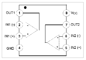
Fig. 10: Pin Diagram of LM358M OPAM IC
For making the sensor module, the IR transmitters are connected in series with pull-up resistors of 470 ohm between VCC and ground in forward bias configuration. The IR receivers are connected in series with variable resistors between VCC and ground in reverse bias configuration forming a voltage divider circuit. The output from the IR receivers (photodiodes) are drawn from the junction of cathode terminals of the IR receiver and variable resistors. Such five pairs of IR receiver and transmitter are connected between VCC and ground to form an IR sensor array. The output from the five IR receivers is connected to the pins 6, 7, 11, 12 and 13 of the Arduino UNO via OPAM comparators. The sensor modules mounted on left side of the robot are interfaced to pins 13 and 12 of the Arduino. The sensor modules mounted on right side of the robot are interfaced to pins 7 and 6 of the Arduino. The sensor mounted on the front side of the robot is interfaced to the pin 8 of the Arduino.
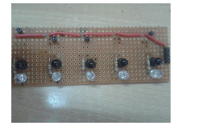
Fig. 11: Image of IR Sensor Array
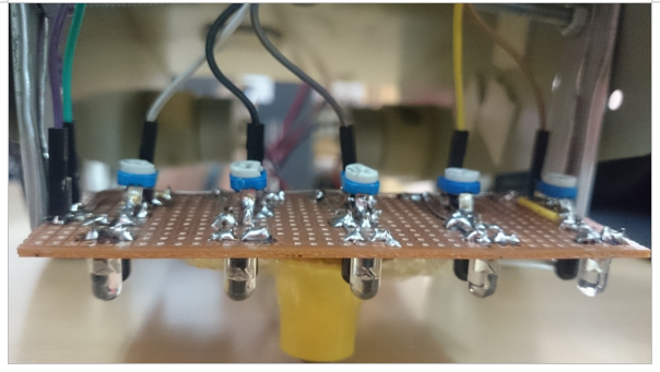
Fig. 12: Image showing IR Sensor Array Mounted on Robot
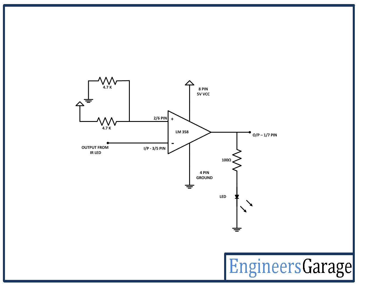
For proper digital output from the IR receivers, the output from the IR receivers is first connected to the inverting input of an operational amplifier. The non-inverting input of the operational amplifier is provided a reference voltage half the HIGH digital logic (5V for the microcontroller circuit) by connecting two 4.7 K ohm resistors between VCC and ground and connecting the resistive junction with the non-inverting input. Then the output pin of the OPAM is connected to the microcontroller pin. The same is done for all the five IR sensors. The operational amplifier is used in the circuit for comparison of the output of IR receiver with the HIGH and LOW digital logic where the reference voltage is set as the half of the HIGH digital logic. So, each OPAM works as a voltage comparator to output a digital logic at the corresponding Arduino pin.
The OPAM is used as negative voltage comparator in the circuit as the reference voltage is set at the non-inverting input and the input voltage from the IR receiver is applied at the inverting input. In such configuration, when the voltage at the inverting input is lower than the reference voltage at the non-inverting input, the output of the OPAM is HIGH while when the voltage at the inverting input of the OPAM is higher than the reference voltage at the non-inverting input, the output of the OPAM is LOW.
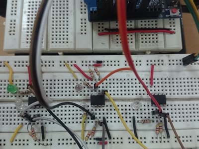
Fig. 13: Image showing OPAM Circuit assembled on Breadboard
The input from the IR sensor module is drawn from the junction of 10K variable resistor and the IR receiver. When the IR radiation from the IR transmitter is incident on walls, it is reflected back and absorbed by the IR receiver (Photodiode). This reduces the resistance of the IR receiver, and there is less voltage drop across it. As a result, more voltage is dropped across the variable resistor which is output by the sensor. So there is less voltage output by the sensor module, the voltage at the inverting input is less than the reference voltage resulting in a HIGH output from the OPAM.
When the IR radiation from the IR transmitter is not incident on the wall, it is gone away and no IR radiation is reflected back to the IR receiver (Photodiode). This increases the resistance of the IR receiver, and there is more voltage drop across it. As a result, less voltage is dropped across the variable resistor and higher voltage is output by the sensor. When there is higher voltage output by the sensor module, the voltage at the inverting input is higher than the reference voltage resulting in a LOW output from the OPAM.
How the circuit works –
The maze solving robot detects the walls by using the IR sensor module and moves the robot close to the wall, until it finds a no wall region. The array of IR sensors has 2 IR sensors on the left side of the robot, two IR sensors on the right side of the robot and one IR sensor in the front of the robot. The IR sensors allow detecting side walls and obstacles in front of the robot.
When the robot finds a no wall space on left side i.e. sensors on left side of the robot detect a no wall region, it turns left and when the robot finds a no wall space on right side i.e. sensors on right side of the robot detect a no wall region, it turns right. It keeps moving along a left side wall or right side wall until it finds an obstacle in the path or find an escape route. When an obstacle is detected in front of the robot, it moves away in the opposite direction until it overcomes the obstacle. As the robot finds a path by detecting absence of a side wall, it turns in that direction moving forward to solve the maze.
The robot can be moved forward, backward, left or right by implementing the following input logic at the motor driver pins –
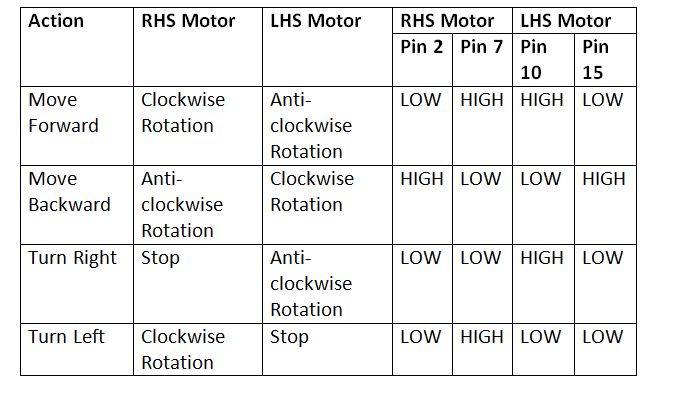
Fig. 14: Logic Table of L293D Motor Driver IC for Maze Solving Robot
The program code not only allows moving the robot in the maze, it also tracks and measures the path followed by the robot and has function to replay the path followed by the robot. Check out the program code to learn how it implements the maze solving algorithm and traces its path along the maze.
Programming Guide –
The Arduino sketch begins with the declaration of the constants used for assigning the Arduino pins interfaced with the IR sensors. It is followed by the declaration of variables that are used to store digital output of each sensor and variables representing the motor driver IC connections. Some variables are declared to store the length of the path followed by the robot.
This is followed by calling a setup() function in which the pins interfaced with the IR sensors are configured to digital input while pins interfaced with the motor driver IC are configured to digital output. The default logics are assigned to the pins in the same function. This function is only called when the robot is first powered on to solve a maze.
After the setup() function, loop() function is called which iterates infinitely to solve the maze and record the path of the robot. In the loop() function, first the sensor values are read by calling readSensors() function and then the digital logic output from the sensors are used to move the robot either in straight direction or to follow left hand side wall. For keep moving the robot in straight direction until it encounters a wall, straight() function is called. The robot starts by following a left side wall otherwise.
void loop()
{
readSensors();
if(leftFarReading == LOW && rightFarReading == LOW &&
(CenterReading == HIGH || leftNearReading == HIGH) )
{
straight();
}
else
{
leftHandWall();
}
}
The robot keeps moving along the left side wall depending upon the presence or absence of the wall and calls straight(), turnleft() and turnright() functions depending upon different situations encountered by the robot. It calls the done() function once it successfully escapes from the maze.
The turnLeft() function is used to move turn the robot on left side.
void turnLeft()
{
.
.
.
}
The turnRight() function is used to move turn the robot on left side.
void turnRight()
{
.
.
.
}
The straight() function is used to keep moving the robot in straight direction.
void straight()
{
.
.
.
}
The turnAround() function is used to overcome an obstacle in the path of the robot.
void turnAround()
{
.
.
.
}
The shortPath() method is used to trace the path followed by the robot and minimize the path length where ever possible.
void shortPath()
{
.
.
.
}
The printPath() method prints the path followed by the robot.
void printPath()
{
.
.
.
}
The replay() method is used to replay the path followed by the robot.
void replay()
{
.
.
.
}
This completes the Arduino sketch for the Maze Solving Robot.
Project Source Code
###
//Program to #define leftFarSensor 13 #define leftNearSensor 12 #define CenterSensor 11 #define rightNearSensor 7 #define rightFarSensor 6 int leftNearReading; int leftFarReading; int CenterReading; int rightNearReading; int rightFarReading; int leftNudge; int replaystage; int rightNudge; #define leapTime 200 #define leftMotor1 2 #define leftMotor2 3 #define rightMotor1 4 #define rightMotor2 5 #define en1 9 #define en2 10 char path[30] = {}; int pathLength; int readLength; void setup() { pinMode(leftNearSensor, INPUT); pinMode(leftFarSensor, INPUT); pinMode(CenterSensor, INPUT); pinMode(rightNearSensor, INPUT); pinMode(rightFarSensor, INPUT); pinMode(leftMotor1, OUTPUT); pinMode(leftMotor2, OUTPUT); pinMode(rightMotor1, OUTPUT); pinMode(rightMotor2, OUTPUT); pinMode(en1, OUTPUT); pinMode(en2, OUTPUT); analogWrite(en1, 160); analogWrite(en2, 160); //Serial.begin(115200); delay(1000); } void loop() { readSensors(); if(leftFarReading == LOW && rightFarReading == LOW && (CenterReading == HIGH || leftNearReading == HIGH) ) { straight(); } else { leftHandWall(); } } void readSensors() { leftNearReading = digitalRead(leftNearSensor); leftFarReading = digitalRead(leftFarSensor); CenterReading = digitalRead(CenterSensor); rightNearReading = digitalRead(rightNearSensor); rightFarReading = digitalRead(rightFarSensor); // serial printing below for debugging purposes // Serial.print("leftCenterReading: "); // Serial.println(leftCenterReading); // Serial.print("leftNearReading: "); // Serial.println(leftNearReading); // Serial.print("leftFarReading: "); // Serial.println(leftFarReading); // Serial.print("rightCenterReading: "); // Serial.println(rightCenterReading); // Serial.print("rightNearReading: "); // Serial.println(rightNearReading); // Serial.print("rightFarReading: "); // Serial.println(rightFarReading); // delay(200); } void leftHandWall() { if(leftFarReading == HIGH && rightFarReading == HIGH){ digitalWrite(leftMotor1, HIGH); digitalWrite(leftMotor2, LOW); digitalWrite(rightMotor1, HIGH); digitalWrite(rightMotor2, LOW); delay(300); readSensors(); if(leftFarReading == LOW && rightFarReading == LOW) { turnLeft(); } else { done(); } } if(leftFarReading == HIGH) { digitalWrite(leftMotor1, HIGH); digitalWrite(leftMotor2, LOW); digitalWrite(rightMotor1, HIGH); digitalWrite(rightMotor2, LOW); delay(300); readSensors(); if(leftFarReading == LOW && rightFarReading == LOW) { turnLeft(); } else { done(); } } if(rightFarReading == HIGH) { digitalWrite(leftMotor1, HIGH); digitalWrite(leftMotor2, LOW); digitalWrite(rightMotor1, HIGH); digitalWrite(rightMotor2, LOW); delay(300); readSensors(); if(leftFarReading == HIGH) { delay(leapTime-30); readSensors(); if(rightFarReading == HIGH && leftFarReading == HIGH) { done(); } else if(rightFarReading == LOW && leftFarReading == LOW && CenterReading == LOW && rightNearReading == LOW) { turnRight(); } else { straight(); return; } } delay(leapTime-30); readSensors(); if(leftFarReading == LOW && CenterReading == LOW && rightFarReading == LOW){ turnRight(); return; } path[pathLength]='S'; // Serial.println("s"); pathLength++; //Serial.print("Path length: "); //Serial.println(pathLength); if(path[pathLength-2]=='B') { //Serial.println("shortening path"); shortPath(); } straight(); } readSensors(); if(leftFarReading == LOW && CenterReading == LOW && rightFarReading == LOW && leftNearReading == LOW && rightNearReading == LOW) { turnAround(); } } void done() { digitalWrite(leftMotor1, LOW); digitalWrite(leftMotor2, LOW); digitalWrite(rightMotor1, LOW); digitalWrite(rightMotor2, LOW); replaystage=1; path[pathLength]='D'; pathLength++; delay(1500); replay(); } void turnLeft() { while(digitalRead(leftNearSensor) == HIGH) { digitalWrite(leftMotor1, LOW); digitalWrite(leftMotor2, LOW); digitalWrite(rightMotor1, HIGH); digitalWrite(rightMotor2, LOW); delay(2); digitalWrite(leftMotor1, LOW); digitalWrite(leftMotor2, LOW); digitalWrite(rightMotor1, LOW); digitalWrite(rightMotor2, LOW); delay(1); } while(digitalRead(leftNearSensor) == LOW) { digitalWrite(leftMotor1, LOW); digitalWrite(leftMotor2, LOW); digitalWrite(rightMotor1, HIGH); digitalWrite(rightMotor2, LOW); delay(2); digitalWrite(leftMotor1, LOW); digitalWrite(leftMotor2, LOW); digitalWrite(rightMotor1, LOW); digitalWrite(rightMotor2, LOW); delay(1); } while(digitalRead(leftFarSensor) == HIGH && digitalRead(leftNearSensor) == HIGH) { digitalWrite(leftMotor1, LOW); digitalWrite(leftMotor2, LOW); digitalWrite(rightMotor1, HIGH); digitalWrite(rightMotor2, LOW); delay(2); digitalWrite(leftMotor1, LOW); digitalWrite(leftMotor2, LOW); digitalWrite(rightMotor1, LOW); digitalWrite(rightMotor2, LOW); delay(1); } if(replaystage==0){ path[pathLength]='L'; //Serial.println("l"); pathLength++; //Serial.print("Path length: "); //Serial.println(pathLength); if(path[pathLength-2]=='B'){ //Serial.println("shortening path"); shortPath(); } } } void turnRight() { while(digitalRead(rightNearSensor) == HIGH){ digitalWrite(leftMotor1, HIGH); digitalWrite(leftMotor2, LOW); digitalWrite(rightMotor1, LOW); digitalWrite(rightMotor2, LOW); delay(1); digitalWrite(leftMotor1, LOW); digitalWrite(leftMotor2, LOW); digitalWrite(rightMotor1, LOW); digitalWrite(rightMotor2, LOW); delay(1); } while(digitalRead(rightNearSensor) == LOW){ digitalWrite(leftMotor1, HIGH); digitalWrite(leftMotor2, LOW); digitalWrite(rightMotor1, LOW); digitalWrite(rightMotor2, LOW); delay(1); digitalWrite(leftMotor1, LOW); digitalWrite(leftMotor2, LOW); digitalWrite(rightMotor1, LOW); digitalWrite(rightMotor2, LOW); delay(1); } while(digitalRead(leftNearSensor) == LOW){ digitalWrite(leftMotor1, HIGH); digitalWrite(leftMotor2, LOW); digitalWrite(rightMotor1, LOW); digitalWrite(rightMotor2, LOW); delay(1); digitalWrite(leftMotor1, LOW); digitalWrite(leftMotor2, LOW); digitalWrite(rightMotor1, LOW); digitalWrite(rightMotor2, LOW); delay(1); } if(replaystage==0){ path[pathLength]='R'; Serial.println("r"); pathLength++; Serial.print("Path length: "); Serial.println(pathLength); if(path[pathLength-2]=='B'){ Serial.println("shortening path"); shortPath(); } } } void straight(){ if( digitalRead(leftNearSensor) == LOW){ digitalWrite(leftMotor1, HIGH); digitalWrite(leftMotor2, LOW); digitalWrite(rightMotor1, HIGH); digitalWrite(rightMotor2, LOW); delay(1); digitalWrite(leftMotor1, HIGH); digitalWrite(leftMotor2, LOW); digitalWrite(rightMotor1, LOW); digitalWrite(rightMotor2, LOW); delay(1); return; } if(digitalRead(rightNearSensor) == LOW){ digitalWrite(leftMotor1, HIGH); digitalWrite(leftMotor2, LOW); digitalWrite(rightMotor1, HIGH); digitalWrite(rightMotor2, LOW); delay(1); digitalWrite(leftMotor1, LOW); digitalWrite(leftMotor2, LOW); digitalWrite(rightMotor1, HIGH); digitalWrite(rightMotor2, LOW); delay(1); return; } digitalWrite(leftMotor1, HIGH); digitalWrite(leftMotor2, LOW); digitalWrite(rightMotor1, HIGH); digitalWrite(rightMotor2, LOW); delay(1); digitalWrite(leftMotor1, LOW); digitalWrite(leftMotor2, LOW); digitalWrite(rightMotor1, LOW); digitalWrite(rightMotor2, LOW); delay(1); } void turnAround(){ digitalWrite(leftMotor1, HIGH); digitalWrite(leftMotor2, LOW); digitalWrite(rightMotor1, HIGH); digitalWrite(rightMotor2, LOW); delay(100); while(digitalRead(leftNearSensor) == LOW || digitalRead(CenterSensor) == LOW){ digitalWrite(leftMotor1, LOW); digitalWrite(leftMotor2, HIGH); digitalWrite(rightMotor1, HIGH); digitalWrite(rightMotor2, LOW); delay(1); digitalWrite(leftMotor1, LOW); digitalWrite(leftMotor2, LOW); digitalWrite(rightMotor1, LOW); digitalWrite(rightMotor2, LOW); delay(1); } path[pathLength]='B'; pathLength++; straight(); //Serial.println("b"); //Serial.print("Path length: "); //Serial.println(pathLength); } void shortPath(){ int shortDone=0; if(path[pathLength-3]=='L' && path[pathLength-1]=='R'){ pathLength-=3; path[pathLength]='B'; //Serial.println("test1"); shortDone=1; } if(path[pathLength-3]=='L' && path[pathLength-1]=='S' && shortDone==0){ pathLength-=3; path[pathLength]='R'; //Serial.println("test2"); shortDone=1; } if(path[pathLength-3]=='R' && path[pathLength-1]=='L' && shortDone==0){ pathLength-=3; path[pathLength]='B'; //Serial.println("test3"); shortDone=1; } if(path[pathLength-3]=='S' && path[pathLength-1]=='L' && shortDone==0){ pathLength-=3; path[pathLength]='R'; //Serial.println("test4"); shortDone=1; } if(path[pathLength-3]=='S' && path[pathLength-1]=='S' && shortDone==0){ pathLength-=3; path[pathLength]='B'; //Serial.println("test5"); shortDone=1; } if(path[pathLength-3]=='L' && path[pathLength-1]=='L' && shortDone==0){ pathLength-=3; path[pathLength]='S'; //Serial.println("test6"); shortDone=1; } path[pathLength+1]='D'; path[pathLength+2]='D'; pathLength++; //Serial.print("Path length: "); //Serial.println(pathLength); //printPath(); } void printPath(){ Serial.println("----------------"); int x; while(x<=pathLength){ Serial.println(path[x]); x++; } Serial.println("-----------------"); } void replay(){ readSensors(); if(leftFarReading == LOW && rightFarReading == LOW){ straight(); } else{ if(path[readLength]=='D') { digitalWrite(leftMotor1, HIGH); digitalWrite(leftMotor2, LOW); digitalWrite(rightMotor1, HIGH); digitalWrite(rightMotor2, LOW); delay(100); digitalWrite(leftMotor1, LOW); digitalWrite(leftMotor2, LOW); digitalWrite(rightMotor1, LOW); digitalWrite(rightMotor2, LOW); endMotion(); } if(path[readLength]=='L') { digitalWrite(leftMotor1, HIGH); digitalWrite(leftMotor2, LOW); digitalWrite(rightMotor1, HIGH); digitalWrite(rightMotor2, LOW); delay(300); turnRight(); } if(path[readLength]=='L'){ digitalWrite(leftMotor1, HIGH); digitalWrite(leftMotor2, LOW); digitalWrite(rightMotor1, HIGH); digitalWrite(rightMotor2, LOW); delay(300); turnLeft(); } if(path[readLength]=='S'){ digitalWrite(leftMotor1, HIGH); digitalWrite(leftMotor2, LOW); digitalWrite(rightMotor1, HIGH); digitalWrite(rightMotor2, LOW); delay(300); straight(); } readLength++; } replay(); } void endMotion() { endMotion(); }###
Circuit Diagrams
Project Video
Filed Under: Electronic Projects
Filed Under: Electronic Projects


Questions related to this article?
👉Ask and discuss on EDAboard.com and Electro-Tech-Online.com forums.
Tell Us What You Think!!
You must be logged in to post a comment.