If you search on Google or youtube for LED chasers, you will find quite a bit of LED chasers.
And here also, by just looking at the title, you will say, “one more LED chaser!!!!… Oh, No, please!!!!”
But wait, wait, wait. This is somewhat different.
Most of the LED chasers are of single colour LED (also of RED LED). Some may be built using microcontrollers, or some may be built using IC NE555 and counter chips (CD4017). There are a limited number of chasing effects and very few features.
The project presented here generates different chasing effects on 35 multicolour LEDs using an Arduino microcontroller board. It also has a potentiometer (pot) to vary the blinking speed of LEDs that will increase or decrease the LED blinking rate and add one more feature to this LED chaser.
Some of the features of this LED chaser are
- 35 multicolour LEDs. 35 more can be connected to other remaining I/O lines
- Programmable chasing effects. More and more effects can be added
- LED blinking rate means chasing effect speed can be varied with the help of pot
- Arduino based easy development platform
So do you want to build this superb LED chaser? It will be straightforward as well as fascinating stuff. So are you ready? First, collect the required components and items
- Arduino UNO/NANO development board
- 35 different colour LEDs – 10 green, ten red, ten blue, and five yellow (you may choose other colour LEDs also)
- ULN2003A chip
- 10 KΩ potentiometers
- Breadboard or general-purpose PCB
- Connecting wires – jumpers
- Soldering iron and solder wire
Now build the circuit of the ULN2003A chip and 35 LEDs on a breadboard or general-purpose PCB as per the given circuit diagram and make connections with the Arduino board as shown.
Circuit diagram
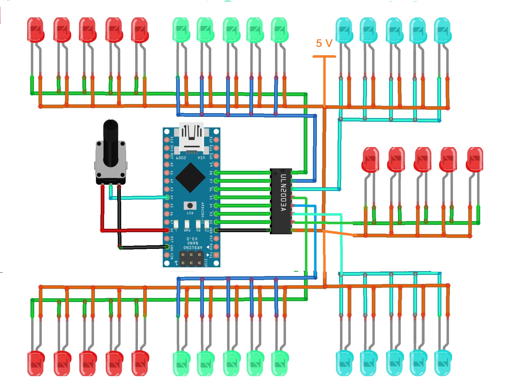
Description
- As shown in the figure, there are seven lines (7 outputs of ULN2003A chip), and in each line, 5 LEDs are connected in parallel. Anode terminals are connected to +5 V, and cathode terminals are connected to outputs of the current driver chip ULN2003A
- One 10 K pot is connected to analog input pin A0, as shown. Its two end terminals are connected to Vcc and Gnd; the middle slider terminal is connected to pin A0. So as the pot is varied from min to max, the analog voltage input varies from 0 to 5 V
- Digital outputs D2 to D8 are connected to inputs of the current driver chip ULN2003A. These pins drive LEDs
- ULN2003A chip and all LEDs are given external 5 V supply other than Arduino board. Ground pin 8 of ULN2003A is connected with Arduino board ground.
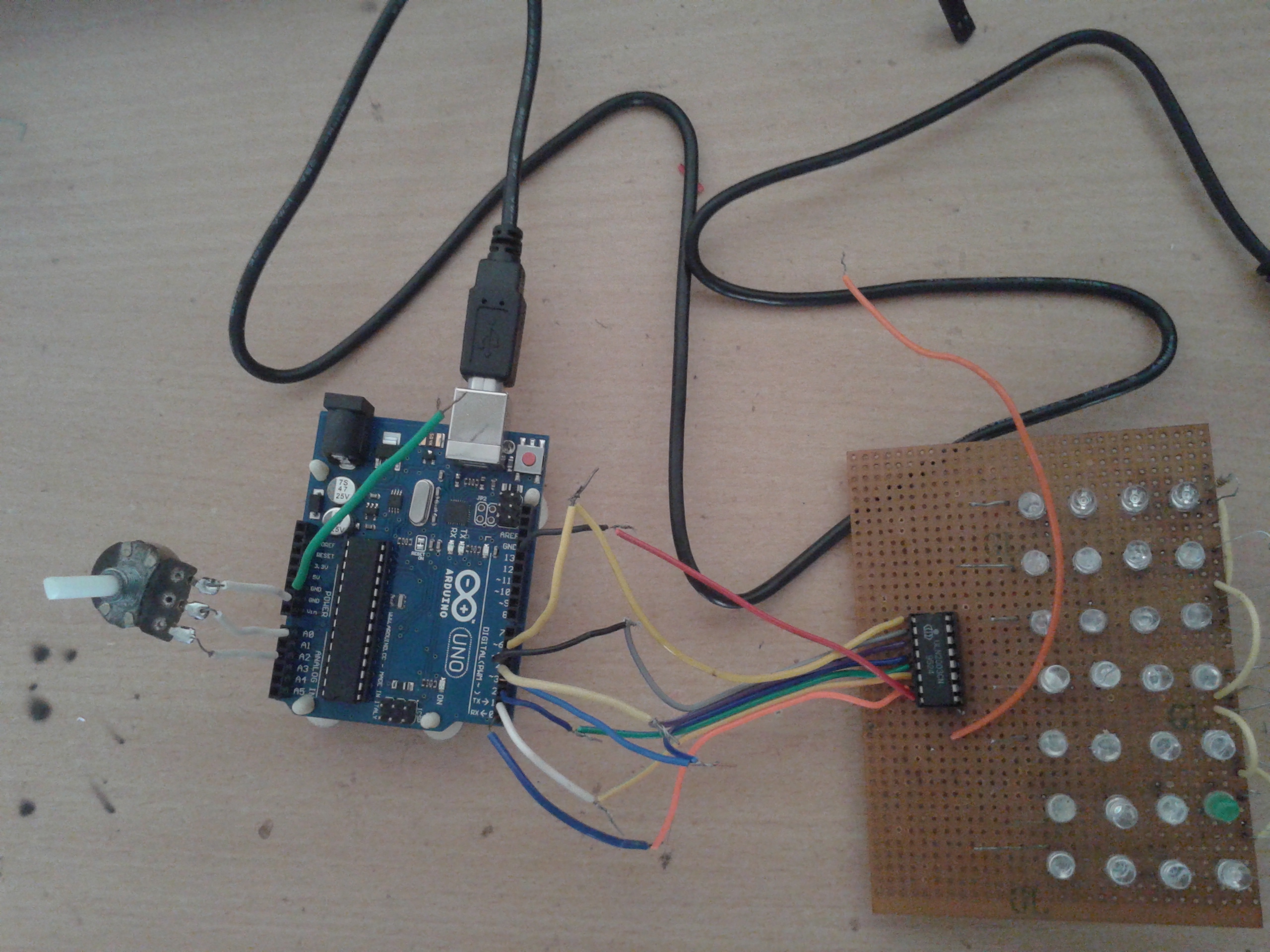
Here is the snap of the circuit arrangement.
Operation
- Four different chasing effects will repeat continuously, like effect 1 – effect 2 – effect 3 – effect 4 – effect 1 – effect 2 – ….. likewise.
- The time period of the effect depends upon the LED blinking delay. The led blinking delay is increased or decreased by varying pot. If the pot is minimum – the delay is minimum – the speed of led blinking is maximum. So the full effect will be over in a short time. But as the pot is increased – the delay also increases – the led blinking speed decreases. So the effect will take a longer time to complete
- As the pot is increased, the analog voltage input increases. So the corresponding value also increases from 0 to up to 1023. This value is given to the delay function after adding 100. Delay function generates a delay in milliseconds, so the led blinking delay is varied approximately from 100 ms to 1100 ms (≈ 1 sec)
- 1st effect is blinking all LEDs one after another means L1 ON (red LEDs) – L1 OFF & L2 (Yellow LEDs) ON – L2 OFF & L3 (blue LEDs) ON – …. likewise
- 2nd effect is turning ON all LEDs from L1 to L7 and then turning them off from L7 to L1. Means L1 ON – L1 & L2 ON – L1 L2 L3 ON – ….L7 OFF – L7 & L6 OFF – …. likewise
- 3rd effect is turning ON and OFF even, and odd lines alternatively mean L1-L3-L5-L7 ON L2-L4-L6 OFF then L1-L3-L5-L7 OFF L2-L4-L6 ON …… likewise
- 4th effect is blinking LEDs from both ends to center means L1 & L7 ON – L2 & L6 ON – L3 & L5 ON – L4 ON – L1 & L7 ON – ….. likewise
Software program
This operation is based on the program loaded into the Arduino board through the Arduino IDE software tool. The following program is compiled and uploaded into the internal flash of onboard microcontroller ATMega328.
Your tube video link for the project
You may also like:


Filed Under: Electronic Projects

Questions related to this article?
👉Ask and discuss on EDAboard.com and Electro-Tech-Online.com forums.
Tell Us What You Think!!
You must be logged in to post a comment.