Summary:
Sometimes Electronics hobbyist gets ideas to build robots from animals in nature. There are robot dogs, robot snakes, robot birds, and even robotic insects! In this project, you will build a robot of your own which will automatically drive chases a light source, mimicking a behavior called photo-taxis, seen in some insects and flowers. This is a robot that chases light, for this to work, the robot needs at least two lights detecting sensors, out in front and spaced apart from each other.
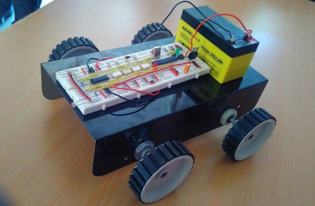
Fig. 1: Prototype of Light Following Arduino Robot
Description:
Prerequisites & Equipment:
You are going to need the following:
-
An Arduino Board or Arduino clone(Here is a guide if you need)
-
Two DC Motors.
-
A 5v TTL -UART Bluetooth module.
-
Robot chassis and wheels which suit your chassis size and motor size.
-
Arduino IDE for the programming.
Working Principle:
Arduino Clone is used here to read the Light intensity of these two Photoresistors and make a comparison and drive the robot in the direction of light. For example, if both photoresistors are getting the same lighter, then the robot should drive straight. If the right photoresist or get more light than right robot should turn towards the right.
Another specialty of this design is by using the same code and some modifications in the hardware we can make the robot avoid objects, by means of bending down the Photoresistor to the ground so that we can make use of shadows of the object to avoid the object by avoiding darkness.
This Photovore robot can also be changed to Photophobe robot by simply reversing the connection of motors i.e. right motor connection to the left and reversing the positive and negative terminals also.

Fig. 2: Block Diagram of Light Following Arduino Robot
The sensor we are using here is a light dependent resistance (LDR) which exhibits Photoconductivity. Its resistance increases with the decrease in light intensity and vice versa. To use them as a sensor we have to measure the voltage drop across the LDR. Because the change in resistance means a change in voltage.
Two different voltage divider principle ways to implement this one is Voltage increases with Light. (R*Vin)/(R+Rphoto) = Vout
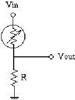
Fig. 3: Circuit Diagram of Light Sensitive Voltage Divider Network
Another one is Voltage decreases with Light. (Rphoto *Vin)/(R+Rphoto) = Vout
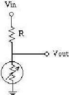
Fig. 4: Circuit Diagram of Dark Sensitive Voltage Divider Network
Three steps are there to determine what resistor we should use for R. To do this, we first need to measure the resistance across the Photoresistor in two situations using a multimeter. The first situation is the darkest light of the Robot. The second situation is the brightest light of the Robot. Now, we need to multiply both resistance values, finding the square root of the total will give the value of the resistor you should use.
Hardware assembly:
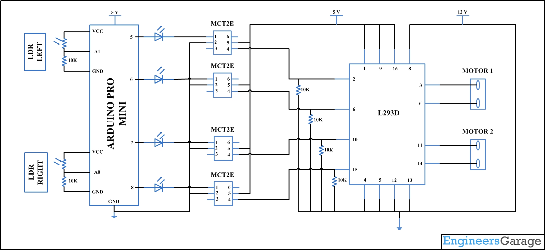
Make the circuit as is given by the circuit diagram. Make the robot assembly with your selected parts and connect the motors to the circuit. Optocouplers are used to safeguard the Arduino from High voltage risks.
Code description:
void setup() {
sensorValue1 = analogRead(LDR1);
sensorValue2 = analogRead(LDR2);
LEFT = sensorValue1/100;
RIGHT = sensorValue2/100;
NLEFT = LEFT;
NRIGHT = RIGHT;
}
The above part of the code is to measure the normal light intensity and storing that value for future comparison and making the robot stable.
The below conditions are used to navigate the Robot:
if ((LEFT == NLEFT) && (RIGHT == NRIGHT))
Condition to compare present LDR values to the normal LDR values, to stop the robot when there is no change.
if ((LEFT > NLEFT) && (RIGHT > NRIGHT)&&(RIGHT == LEFT))
Condition to move the robot forward if both the LDR values are increased.
if ((RIGHT > LEFT)&&((LEFT > NLEFT) || (RIGHT > NRIGHT)))
Condition to move the robot Right if both the LDR values are increased.
if ((LEFT > RIGHT)&&((LEFT > NLEFT) || (RIGHT > NRIGHT)))
Condition to move the robot Left if both the LDR values are increased.
You may also like:
Circuit Diagrams
Project Video
Filed Under: Electronic Projects
Filed Under: Electronic Projects





Questions related to this article?
👉Ask and discuss on EDAboard.com and Electro-Tech-Online.com forums.
Tell Us What You Think!!
You must be logged in to post a comment.