An autonomous robot is a robot that is capable of moving on its own in an unknown and unstructured environment. An autonomous robot is equipped with software intelligence to sense its environment, detect obstacles in its path and move around an unknown environment overcoming the obstacles. There are many robotic designs that are employed in designing of autonomous robots. These designs are usually developed considering the physical environment in which the robot has to be deployed. There are autonomous robots like snake robots, walking robots, autonomous drones and autonomous robotic cars or rovers.
In this tutorial, an autonomous robotic car is designed. The robotic car uses an ultrasonic sensor to sense its environment and detect obstacles. The robot can rotate the ultrasonic sensor from 0 degree to 180 degrees with the help of a servo motor and find an escape route by measuring distance on its left and right side. The robot automatically turns left or right depending upon the side at which there is no obstacle or a path obstruction is at a greater distance. The robot is designed to move around an obstacle detected in front of it. The robotic car designed in this project runs on two geared DC motors and is powered by the battery.
The control circuitry of the robot is built on Arduino UNO. The ultrasonic sensor, servo motor and motor driver IC coupled with two geared DC motors are interfaced with the Arduino board. The Arduino sketch initializes the robot to move in forward direction and manages to detect any obstacle in front of the robot, rotate ultrasonic sensor with help of servo motors, measure distance on left side and right side and turn robot either left or right where ever there is more distance available to move around. The Arduino sketch has been written and compiled using Arduino IDE. The control circuitry is assembled and mounted on a two-wheel and a castor robot.

Fig. 1: Prototype of Arduino based Autonomous Robot
Components Required –

Fig. 2: List of components required for Arduino based Autonomous Robot
Block Diagram –
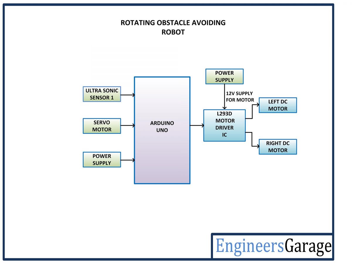
Fig. 3: Block Diagram of Arduino based Autonomous Robot
Circuit Connections
The control circuitry of this autonomous robot is built around Arduino UNO. The ultrasonic sensor, servo motor and motor driver IC coupled with two geared DC motors are interfaced with the Arduino board. The control circuitry has the following components and circuit connections –
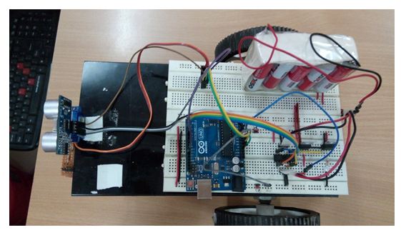
Fig. 4: Image showing Arduino based Control Circuit Mounted on Autonomous Robot
Power Supply – In the circuit, Arduino UNO, servo motor and the ultrasonic sensor need a 5V regulated DC for their operation while the motor driver IC needs 12V DC. A 12V NIMH battery is used as the primary source of power. The supply from the battery is regulated to 5V and 12V using 7805 and 7812 ICs. The pin 1 of both the voltage regulator ICs is connected to the anode of the battery and pin 2 of both ICs is connected to ground. The respective voltage outputs are drawn from pin 3 of the respective voltage regulator ICs. An LED along with a 10K Ω pull-up resistor is also connected between common ground and output pin to get a visual hint of supply continuity. Despite using 12V battery, 7812 is used to provide a regulated and stable supply to the motor driver IC.
Arduino UNO – Arduino UNO is one of the most popular prototyping boards. It is used frequently in robotic applications as it is small in size and packed with rich features. The board comes with built-in Arduino boot loader. It is an Atmega 328 based controller board which has 14 GPIO pins, 6 PWM pins, 6 Analog inputs and on board UART, SPI and TWI interfaces. In this project, 6 GPIO pins of the board are utilized to interface the motor driver IC, one GPIO pin is used to interface servo motor and 2 GPIO pins are used to interface the ultrasonic sensor.
HC-SR04 Ultrasonic Sensor – The HC-SR04 ultrasonic sensor uses sonar to determine the distance to an object like bats or dolphins do. It offers excellent non-contact range detection with high accuracy and stable readings in the range from 2 cm to 400 cm.
There is an ultrasonic sensor used in the circuit mounted in front of the robot. The ultrasonic sensor mounted on the front is connected to pins A0 and A1 of the Arduino board. The ultrasonic sensor has four pins – Ground (Pin 1), Echo (Pin 2), Trigger (Pin 3) and Trigger. The VCC and ground pins are connected to common VCC and Ground respectively. The Echo pin of the sensor is connected to pin A1 and Trigger pin is connected to pins A0 of the Arduino board.
The ultrasonic sensor works on the principle of echo of sound waves. When a HIGH pulse of 10 u sec is passed to the trigger pin of the sensor, it transmits eight 40 KHz waves of HIGH Sonic Pulse shots back to back. A High pulse signal is out from the echo pin as the ultrasonic wave is transmitted. This wave when collides with an obstacle, it is reflected back and detected by the sensor.
On detecting the wave again, the High pulse signal from the echo pin of the sensor is terminated. The signal received from the echo pin is analog in nature. The distance from the obstacle can be measured by measuring the high time of the echo pin. This is the time between the transmission and reflection back of the sonic wave. The distance is given by the formulae –
Test distance = (high level time × velocity of sound (340M/S)) / 2
The time multiplied by velocity is divided by 2 as the time taken is for sonic wave to reach obstacle and return back. Therefore the distance measurement in cm can be given by the formulae –
Test distance = (high level time × velocity of sound (340M/S)) / 2
= (high level time(microsecond) × velocity of sound (340M/S)) / 2
= high level time x 340/2000000 m
= high level time x 34000/2000000 cm
= high level time x 34/2000 cm
The ultrasonic sensor outputs the high pulse from its pin 2 which is detected at the pin A1 of the Arduino Board. The program code measures the pulse durations and digitize them to distance values using the formulae stated above.
The robot initially has the ultrasonic sensor facing the front side. when it detects an obstacle in front of the robot, it rotates the sensor to left and right side measuring distance on both sides. The distance values are utilized to determine whether robot should turn left or right to find an escape route.

Fig. 5: Image of Ultrasonic sensor mounted over Servo Motor
Servo motor – The servo motor is used to rotate the ultrasonic sensor from front to left side and then to right side and front again. The servo motor has three terminals – VCC, Ground and Control. The VCC and Ground are connected to common VCC and Ground respectively. The control terminal of the motor is connected to pin 11 of the Arduino board. A pulse width modulated signal need to be passed to the control terminal of the servo in order to rotate it between angles 0 and 180 degrees. That is why servo motor used in the project is SG-9 which can rotate between 0 and 180 degrees.
L293D DC Motor Driver IC – The L293D is a dual H-bridge motor driver integrated circuit (IC). The Motor drivers act as current amplifiers since they take a low-current control signal and provide a higher-current signal. This higher current signal is used to drive the motors. It has 16 pins with following pin configuration:
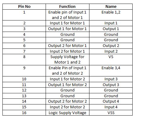
Fig. 6: Table listing pin configuration of L293D Motor Driver IC
There are two DC motors used for making the robotic car. The DC motors are interfaced between pins 3 and 6 and pins 14 and 11 of the motor driver IC.
The L293D IC controls the DC Motors according to the following truth tables:

Fig. 7: Truth Table of L29D Motor Driver IC
The pin 4, 5, 13 and 12 of the L293D are grounded while pin 1, 16 and 9 are connected to 5V DC and pin 8 is connected to 12V DC. The pins 15, 2, 7 and 10 of the motor driver IC are connected to pins 5, 2, 3 and 4 of the Arduino board. The DC motor attached to right wheel is connected to pins 11 and 14 while motor attached to left wheel is connected to pins 3 and 6 of the motor driver IC. The enable pins 1 and 9 of the motor driver IC are connected to pins 9 and 10 of the Arduino UNO.
Geared DC Motors – In this robot, 12V geared DC motors are attached to the wheels. Geared DC motors are available with wide range of RPM and Torque, which allow a robot to move based on the control signal it receives from the motor driver IC.
How the circuit works –
This autonomous robot has very simple functioning. Once the battery is attached to the robot, it gets powered on. As it is powered, it detects any obstacle in front of it. If there is no obstacle in front of the robot, the robot starts moving in the forward direction. When the robot finds an obstacle in front of it, it stops at that spot and the servo motor rotates to 0 degree rotating the ultrasonic senor to left side. The robot measures distance on its left side using ultrasonic sensor once the servo has finished rotation to 0 degree.
Then the robot rotates servo to 180 degrees rotating the ultrasonic senor to right side. The robot measures distance on its right side using ultrasonic sensor once the servo has finished rotation to 180 degree. The distance on left and right side are compared by the Arduino program and the robot turns in the direction in which the distance is greater. The robot turns either left or right overcoming the obstacle in front of it and again turn in the opposite direction to resume its motion in forward direction.
The robot is moved forward, backward, left or right by implementing the following input logic at the motor driver pins –

Fig. 8: Logic Table of L293D Motor Driver IC for Arduino based Autonomous Robot
The robot can slow or speed up in the process of overcoming the obstacles by applying appropriate PWM at the enable pins of the motor driver IC for the respective DC motors. The functioning of the robot is summarized in the following flowchart –
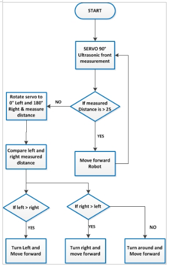
Fig. 9: Flowchart of Programming Algorithm for Autonomous Robot
The detection of obstacle, halting of robot, rotation of servo motor to rotate the ultrasonic sensor, measurement of distance on left and right side and turning of robot around the obstacle are all managed by the Arduino sketch. The Arduino sketch has conditionals to detect obstacle and sense the surrounding conditions and act accordingly. Check out the programming guide and the complete project code to learn about the Arduino code which makes this robot an autonomous explorer.
Programming Guide –
The Arduino sketch begins with import of required libraries. The new ping library is imported for the ultrasonic sensor. Check out the official website of Arduino platform to learn about the new ping library in details. The library can be downloaded from NewPing.h. The Servo.h library is also imported for controlling the servo motor.
#include <NewPing.h>
The variables are declared to assign microcontroller pins according to their interfacing with the ultrasonic sensors, servo and the L293D motor driver IC.

Fig. 10: Screenshot of initialization of Arduino Code for Autonomous Robot
The setup() function is called in which pins connected to the ultrasonic sensor’s echo pin is declared as input and the pin connected to the motor driver IC and trigger pin of ultrasonic sensor are declared as digital output using pinMode() function. The setup() function run only once during the start of the Arduino Sketch.
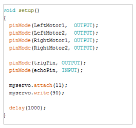
Fig. 11: Screenshot of setup function of Arduino Code for Autonomous Robot
The loop() function is called which iterates infinitely. In the loop() function, the reading of the ultrasonic sensors are fetched using the readsensor() function.

Fig. 12: Screenshot of loop function of Arduino Code for Autonomous Robot
The decidepath() function is used to rotate the servo and measure the distance on left and right side of the robot. The checkdistance() function is used to determine the path that has no obstacle and to choose whether should robot turn left, right or make a turn around.

Fig. 13: Screenshot of decide-path function of Arduino Code for Autonomous Robot
Check out the complete Arduino code for better understanding of the project. Burn the code to an Arduino board, assemble the control circuitry and try a run of the autonomous robot. This completes the programming guide for the Arduino UNO based Autonomous robot.
Project Source Code
###
//Program to #include <Servo.h> #include <NewPing.h> Servo myservo; //define the pins to be connected to ultrasonic sensor #define trigPin A0 #define echoPin A1 //define the pins to be connected to ultrasonic sensor #define LeftMotor1 4 #define LeftMotor2 5 #define RightMotor1 2 #define RightMotor2 3 #define maxdist 300 #define objdist 23 NewPing sonar(trigPin, echoPin, maxdist); int leftDistance, rightDistance; //setup function to define the pinmodes void setup() { pinMode(LeftMotor1, OUTPUT); pinMode(LeftMotor2, OUTPUT); pinMode(RightMotor1, OUTPUT); pinMode(RightMotor2, OUTPUT); pinMode(trigPin, OUTPUT); pinMode(echoPin, INPUT); myservo.attach(11); myservo.write(90); delay(1000); } //Loop infinite function void loop() { int read_dist; //Make servo to turn 90 degree myservo.write(90); delay(90); //calling read sensor function to read the sensor data read_dist = readsensors(); //checking the distance that is measured with the predefined value if(read_dist < objdist) { //if low calling the decide path function decide_path(); } //calling the move forward function to move the robot forward moveforward(); delay(500); } //Function to read the sensor value int readsensors() { int distance; delay(70); //using the newping.h library function to measure the distance unsigned int uS = sonar.ping(); distance = uS/US_ROUNDTRIP_CM; return distance; } void decide_path() { robostop(); //rotating the servo to 3 degree to right side myservo.write(3); delay(500); //calling read sensor function to measure the distance on right side rightDistance = readsensors(); delay(500); myservo.write(180); delay(700); leftDistance = readsensors(); delay(500); myservo.write(90); delay(100); check_distance(); } //function to compare the distances void check_distance() { //checking whether left measured distance is lesser that right if (leftDistance < rightDistance) { turnright(); } //checking whether left measured distance is greater that right else if (leftDistance > rightDistance) { turnleft(); } else { turnaround(); } } void moveforward() { digitalWrite(LeftMotor1, HIGH); digitalWrite(LeftMotor2, LOW); digitalWrite(RightMotor1, HIGH); digitalWrite(RightMotor2, LOW); } void turnleft() { digitalWrite(LeftMotor1, LOW); digitalWrite(LeftMotor2, LOW); digitalWrite(RightMotor1, HIGH); digitalWrite(RightMotor2, LOW); delay(350); moveforward(); } void turnright() { digitalWrite(LeftMotor1, HIGH); digitalWrite(LeftMotor2, LOW); digitalWrite(RightMotor1, LOW); digitalWrite(RightMotor2, LOW); delay(350); moveforward(); } void turnaround() { digitalWrite(LeftMotor1, LOW); digitalWrite(LeftMotor2, HIGH); digitalWrite(RightMotor1, HIGH); digitalWrite(RightMotor2, LOW); delay(700); moveforward(); } void robostop() { digitalWrite(LeftMotor1, LOW); digitalWrite(LeftMotor2, LOW); digitalWrite(RightMotor1, LOW); digitalWrite(RightMotor2, LOW); }###
Circuit Diagrams
Project Video
Filed Under: Electronic Projects
Filed Under: Electronic Projects


Questions related to this article?
👉Ask and discuss on Electro-Tech-Online.com and EDAboard.com forums.
Tell Us What You Think!!
You must be logged in to post a comment.