Food safety and hygiene is a major concern in order to prevent the food wastage. The Quality of the food needs to be monitored and it must be prevented from rotting and decaying by the atmospheric factors like temperature, humidity and dark. Therefore, it is useful to deploy quality monitoring devices at food stores. These quality monitoring devices keep a watch on the environmental factor that cause or pace up decay of the food. Later, the environmental factors can be controlled like by refrigeration, vacuum storage etc.
In this project, a similar food quality monitoring device will be designed that will keep watch of environmental factors like temperature, humidity, alcohol content and exposure to light. The device is built on Arduino UNO which is a popular prototyping board. The Arduino board is interfaced with various sensors like DHT-11 to monitor temperature and humidity, MQ3 to detect alcohol content and LDR to measure exposure to light. This is an IoT device and sends the measured sensor data to an IoT platform. The ESP8266 Wi-Fi Modem is interfaced with the Arduino to connect it to the internet via Wi-Fi router. The sensor data is also displayed on a character LCD interfaced with the Arduino UNO. The IoT platform used for logging and monitoring of sensor data is Freeboard.io. With the power of Internet of Things, the environmental factors affecting the food storage can be monitored from anywhere, anytime and from any device.
Many such devices can be installed at a location for better monitoring and quality control. The Arduino Sketch running over the device implements the various functionalities of the project like reading sensor data, converting them into strings, displaying them on character LCD and passing them to the IoT platform. The Sketch is written, compiled and loaded using the Arduino IDE.

Fig. 1: Prototype of Arduino Based Smart IoT Food Quality Monitoring System
Components Required –

Fig. 2: List of Components for Arduino Based Smart IoT Food Quality Monitoring System
Block Diagram –

Fig. 3: Block Diagram of Arduino Based Smart IoT Food Quality Monitoring System
Circuit Connections –
The food quality monitoring device designed in this project is based on Arduino UNO.So reader should have knowledge of How to start with Arduino. The Arduino has served as an IoT board in this project. Various sensors like DHT-11, MQ3 and LDR, the ESP8266 Wi-Fi Modem and character LCD are interfaced to the Arduino.
The Arduino based IoT device has the following circuit connections –

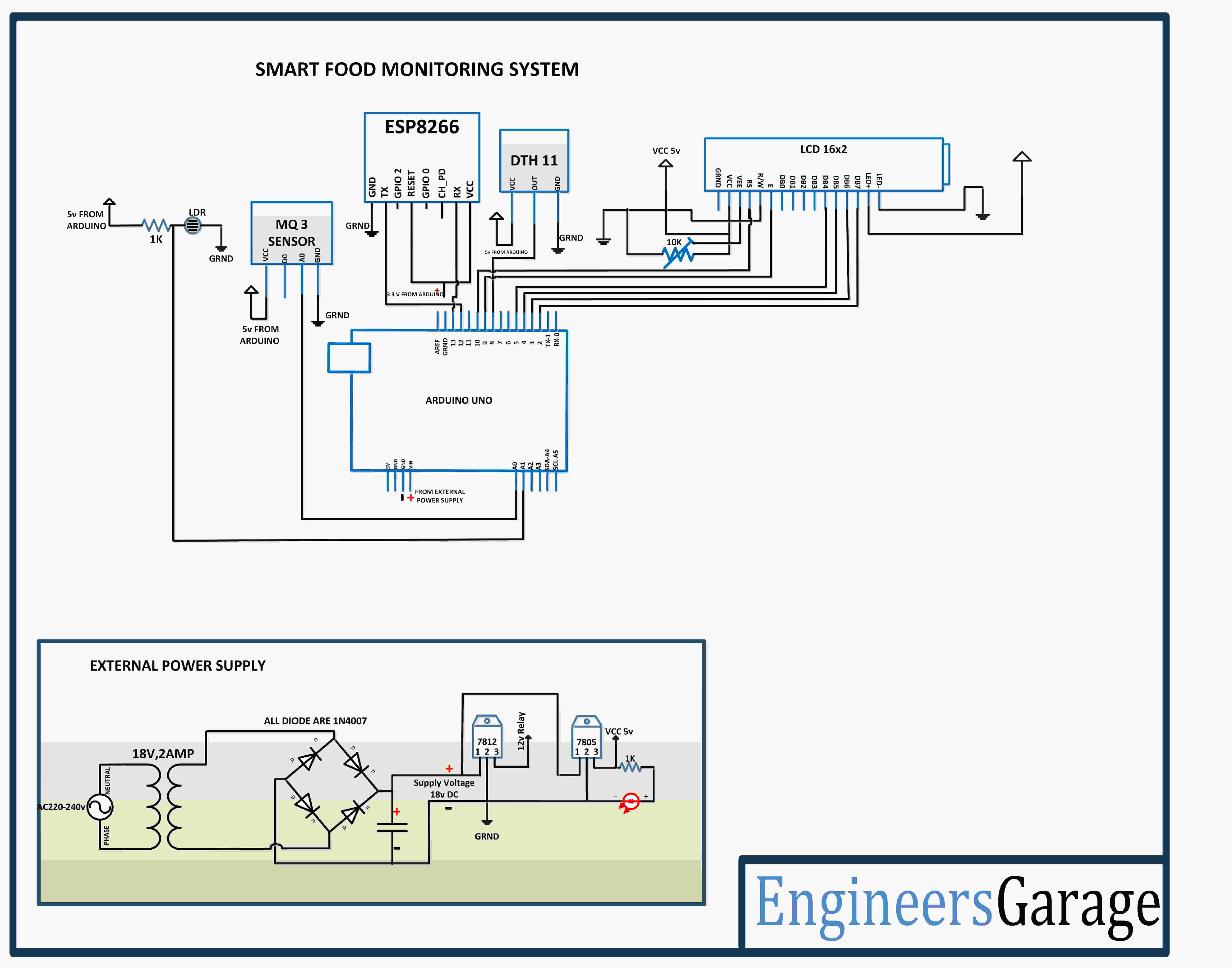
Fig. 4: Image showing circuit connections of Arduino Based Smart IoT Food Quality Monitoring System
Arduino UNO – The Arduino UNO is ATmega328 based microcontroller board. It is one of the most popular prototyping boards. The board comes with built-in arduino boot loader. It has 14 GPIO pins, 6 PWM pins, 6 Analog inputs and on board UART, SPI and TWI interfaces, an on-board resonator, a reset button, and holes for mounting pin headers. While programming the board, it can be connected to the PC using USB port and the board can runs on USB power. The Arduino UNO has 32 Kb Flash memory, 1 Kb EEPROM and 2 Kb SRAM. The board can be connected to different Arduino Shields for connectivity with Ethernet, Bluetooth, Wi-Fi, Zigbee or Cellular network and it can be connected to most of the IoT platforms. The ATmega328 controller has the following pin configuration –

Fig. 5: Table listing pin configuration of Arduino Uno
In this project, the two Analog Input pins of the board are used to interface the LDR and MQ3 sensor, one GPIO is used to interface DHT-11 sensor, two GPIO are used to interface ESP8266 module where pins are configured UART transmitter and receiver pins using software serial and 6 GPIO pins are used to interface the graphic LCD.
DHT-11 Sensor – DHT-11 is a temperature and humidity sensor. The DHT11 sensor consists of two main components – one is Humidity sensing component and other is NTC temperature sensor (or Thermistor). The Thermistor is actually a variable resistor that changes its resistance with change in temperature. They both sense the temperature and humidity of area and give the output to the IC (which is placed on back side of sensor). The sensor has four pins – VCC, Ground, data Out and NC. The VCC and Ground pins are connected to the common VCC and Ground respectively. The Data Out pin of the sensor is connected to PB0 pin of the Arduino board.
MQ3 Sensor – MQ3 alcohol sensor module is used to detect the presence of ethanol, where the sensitive material used for this sensor is SnO2, whose conductivity is lower in clean air. It’s conductivity increases as the concentration of ethanol gases increases. It has high sensitivity to alcohol and has a good resistance to disturbances due to smoke, vapor and gasoline. This module provides both digital and analog outputs. It has a high sensitivity and fast response time. Sensor provides an analog resistive output based on alcohol concentration. MQ-3 is an analog as well as digital sensor. The presence of ethanol vapors in food is a sign of decay. So, by MQ3 sensor, it can be detected if food has started decaying. The sensor has four pins – Analog Out, Digital Output, VCC and Ground. The VCC and ground are connected to the common VCC and Ground. The digital output pin is not used therefore is kept not connected. The output of the sensor is drawn from the analog output pin which is connected to the pin A0 of the Arduino board.
LDR Sensor – The LDR is used to sense the intensity of light. The sensor is connected to the A1 pin of the Arduino board. The sensor is connected in a potential divider circuit. The LDR provides an analog voltage which is converted to digital reading by the in-built ADC.
16X2 LCD – The 16X2 LCD display is connected to the Arduino board by connecting its data pins to pins 2 to 5 of the Arduino board. The RS and E pins of the LCD are connected to pins 10 and 9 of the Arduino board respectively. The RW pin of the LCD is grounded.

Fig. 6: Table listing circuit connections between Arduino and LCD
The standard open-source library for interfacing LCD with Arduino board is used in the project. The library works as expected and needs no changes or modifications.
ESP8266 Module – The ESP8266 Wi-Fi Module is a self contained SOC with integrated TCP/IP protocol stack that can access to a Wi-Fi network. The ESP8266 is capable of either hosting an application or off loading all Wi-Fi networking functions from another application processor. Each ESP8266 module comes pre-programmed with an AT command set firmware. The module comes available in two models – ESP-01 and ESP-12. ESP-12 has 16 pins available for interfacing while ESP-01 has only 8 pins available for use. The ESP-12 has the following pin configuration –

Fig. 7: Table listing pin configuration of ESP8266 ESP-12 Modem
The ESP-01 model is used in the project. The ESP-01 model has the following pin configuration –

Fig. 8: Table listing pin configuration of ESP8266 ESP-01 Modem
The RESET and VCC pins of the module are connected to the 3.3 V DC while Ground pin is connected to the common ground. The Tx and Rx pins of the module are connected to the 12 and 13 pins of the Arduino UNO.
Power Supply – The circuit operates on 5V DC. The AC mains is used as the primary source of power. The supply from the mains is stepped down by a transformer and rectified by a full-bridge rectifier. The rectified output is regulated to 5V and 12V using 7805 and 7812 ICs. The pin 1 of both the voltage regulator ICs is connected to the anode of the battery and pin 2 of both ICs is connected to ground. The respective voltage outputs are drawn from pin 3 of the respective voltage regulator ICs. An LED along with a 10K Ω pull-up resistor is also connected between common ground and output pin to get a visual hint of supply continuity.
How the circuit works –
This Arduino based IoT device should be installed in a food store. Once it is properly installed and powered on, it connects with the internet via Wi-Fi modem and start reading data from the interfaced sensors – DHT-11 temperature and humidity sensor, MQ3 Sensor and the LDR sensor.
DHT11 Temperature and Humidity Sensor is a digital sensor with inbuilt capacitive humidity sensor and Thermistor. It relays a real-time temperature and humidity reading every 2 seconds. The sensor operates on 3.5 to 5.5 V supply and can read temperature between 0° C and 50° C and relative humidity between 20% and 95%.
The sensor cannot be directly interfaced to a digital pin of the board as it operates on 1-wire protocol which must be implemented only on the firmware. First the data pin is configured to input and a start signal is sent to it. The start signal comprises of a LOW for 18 milliseconds followed by a HIGH for 20 to 40 microseconds followed by a LOW again for 80 microseconds and a HIGH for 80 microseconds. After sending the start signal, the pin is configured to digital output and 40-bit data comprising of the temperature and humidity reading is latched out. Of the 5-byte data, the first two bytes are integer and decimal part of reading for relative humidity respectively, third and fourth bytes are integer and decimal part of reading for temperature and last one is checksum byte.
For Arduino, standard library for DHT-11 sensor is already available. The data from the sensor can be easily ready by calling read11() method of the DHT class.
The LDR sensor is connected in a potential divider circuit and inputs a voltage at the analog input pin of the controller. The voltage is read and digitized using in-built ADC channel.
The MQ3 sensor detects the emission of ethanol type of gases. If the food/fruits get spoiled, they emit the ethanol type of gases. The MQ3 sensor detects the concentration of such gases and output an analog voltage proportional to the concentration of the gas. The analog output is passed to the analog pin of the Arduino which has inbuilt ADC that coverts the analog to digital value.
The Arduino collects data from all the sensors and convert the values to the strings. The sensor data wrapped as proper strings are passed to the character LCD for display. The ESP8266 Wi-Fi module connected to the Arduino uploads the data to ThingSpeak Server. For displaying and monitoring data uploaded to the ThingSpeak server, either a digital dashboard or data broker is needed. In this project, a digital dashboard called Freeboard.io is used to monitor the sensor data visually online. The Freeboard.io use JASON file to visualize ThingSpeak data. It offers three elements to build a dashboard –
1) Data Sources – The data sources get the data from external sources. These external sources can be data broker services, JavaScript applications or JSON files receiving content from an HTTP server. In this project, the data source is a JSON file that receives data from the ThingSpeak server.
2) Widgets – The Widgets help to display data in textual or graphical form. There are many widgets available in Freeboard.io like text, graph, gauge etc.
3) Panes – These are used to organize widgets.
Freeboard.io requires sign up and after sign widgets can be created.

Fig. 9: Screenshot of Freeboard Sign Up Page
There are four gauge type widgets created to monitor temperature, humidity, light intensity and ethanol gas concentration. On Freeboard.io, these widgets look like as follow –

Fig. 10: Screenshot of Gauge Type Widgets on Freeboard API
The dashboard on Freeboard.io can be created as follow –
1. Go to freeboard.io website and sign up with a new account.
2. Enter the name and click on the create button, after entering into the new window, click on the create data source and select type as JASON.

Fig. 11: Screenshot of making data source selection on Freeboard API
3. After that fill the fields as shown in below image. In the URL tab shown in the image, change the number 392797 with the respective channel id.

Fig. 12: Screenshot of Setting Data Source on Freeboard.io to ThingSpeak Platform
4. After creating the data source, click on add pane and select as Gauge.

Fig. 13: Screenshot of Widget Creation on Freeboard.io
5. At the pane, after selecting the Gauge select the following as shown below and create the widgets.

Fig. 14: Screenshot of Gauge Widget Creation on Freeboard.io
This way the sensor data can be uploaded on ThingSpeak server and viewed online at Freeboard.io dashboard.
Programming Guide –
The Arduino sketch manages to collect data from the DHT-11, MQ3 and LDR sensor, convert sensor values to string, display them on character LCD and pass data to the ThingSpeak server. First the standard open-source library of Arduino for interfacing DHT11 is imported and software Serial library for serial communication with the Wi-Fi module is imported. The variables representing pin connections to read the sensor data are initialized.

Fig. 15: Screenshot of Initialization in Arduino Code for IoT Food Quality Monitor
The setup() function is called in which baud rate for the serial communication for communication with the Wi-Fi modem is set to 9600. The Wi-Fi mode and network connectivity is established using the AT commands with some delays. The delay should be given according to time it takes to connect with the network.

Fig. 16: Screenshot of Setup Function in Arduino Code for IoT Food Quality Monitor
The loop() function is called in which the sensor data is fetched and stored in the initialized variables. The esp8266() function is called for transmitting data to the cloud.

Fig. 17: Screenshot of Loop Function in Arduino Code for IoT Food Quality Monitor
At the esp8266() function, the AT commands for establishing TCP connection are passed, and then API key of the ThingSpeak is given to transmit a data to the registered channel. At every 16 seconds, the data gets updated to the ThingSpeak channel.

Fig. 18: Screenshot of Function Managing IoT communication in Arduino Sketch for IoT Food Quality Monitor
This completes the Arduino sketch for IOT Based Smart Food Monitoring Project.
Project Source Code
###


//Program to

#include <SoftwareSerial.h>

#include <LiquidCrystal.h>

#include <dht.h>   // include dht sensor library

LiquidCrystal lcd(10, 9, 5, 4, 3, 2);

dht DHT;

float t=0;

float h=0;

#define DHT11_PIN 8

#define LDR_PIN A1

#define MQ3_PIN A0

char data = 0;

int ldr_read = 0;

int gas_read = 0;

// replace with your channel's thingspeak API key

String apiKey = "[API KEY FROM THINGSPEAK]";

// connect 10 to TX of Serial USB

// connect 11 to RX of serial USB

SoftwareSerial ser(12,13); // RX, TX

void setup()

{

  // enable software serial

  ser.begin(9600);

  lcd.begin(16,2);


 // pinMode(LDR_PIN, INPUT);

  //pinMode(MQ3_PIN, INPUT);


  lcd.setCursor(1,0);

  lcd.print("**SmarT FooD**");

  lcd.setCursor(3,1);

  lcd.print("MonitorinG");

  Serial.begin(9600);


  // reset ESP8266 WiFi connection AT+CIPMUX=1 AT+CWJAP

  ser.println("AT");

  delay(1000);

  ser.println("AT+GMR");

  delay(1000);

  ser.println("AT+CWMODE=3");

  delay(1000);

  ser.println("AT+RST");

  delay(5000);

  ser.println("AT+CIPMUX=1");

  delay(1000);

  String cmd="AT+CWJAP="[YOUR SSID]","[PASSWORD]"";

  ser.println(cmd);

  delay(1000);

  ser.println("AT+CIFSR");

  delay(1000);

 }

// the loop

void loop()

{

  lcd.clear();

  ldr_read = analogRead(LDR_PIN);

  lcd.setCursor(0,0);

  lcd.print("LDR-");

  lcd.setCursor(4,0);

  lcd.print(ldr_read);


  lcd.setCursor(0,1);

  lcd.print("MQ3-");

  gas_read = analogRead(MQ3_PIN);

  lcd.setCursor(4,1);

  lcd.print(gas_read);


  int chk = DHT.read11(DHT11_PIN);

  Serial.print("Temperature = ");

  t = DHT.temperature;


  //lcd.clear();

  lcd.setCursor(8,0);

  lcd.print("Tem-");


  lcd.setCursor(12,0);

  lcd.print(t);

  Serial.println(t);


  Serial.print("Humidity = ");

  h = DHT.humidity;

  lcd.setCursor(8,1);

  lcd.print("Hum-");

  lcd.setCursor(12,1);

  lcd.print(h);

  Serial.println(h);


  esp_8266();

}

void esp_8266()

{

   // TCP connection AT+CIPSTART=4,"TCP","184.106.153.149",80

    String cmd = "AT+CIPSTART=4,"TCP","";

    cmd += "184.106.153.149"; // api.thingspeak.com

    cmd += "",80";

    ser.println(cmd);

    Serial.println(cmd);

    if(ser.find("Error"))

    {

      Serial.println("AT+CIPSTART error");

      return;

    }


  // prepare GET string GET https://api.thingspeak.com/update?api_key=LHAG4NSIYJ5UWS6U&field1=0rnrn

  String getStr = "GET /update?api_key=";

  getStr += apiKey;

  getStr +="&field1=";

  getStr +=String(t);

  getStr +="&field2=";

  getStr +=String(h);

  getStr +="&field3=";

  getStr +=String(ldr_read);

  getStr +="&field4=";

  getStr +=String(gas_read);

  getStr += "rnrn";

  // send data length

  cmd = "AT+CIPSEND=4,";

  cmd += String(getStr.length());

  ser.println(cmd);

  Serial.println(cmd);

  delay(1000);

  ser.print(getStr);

  Serial.println(getStr);


  // thingspeak needs 15 sec delay between updates

  delay(3000);

}


###
Circuit Diagrams
Project Video
Filed Under: Electronic Projects, IoT
Filed Under: Electronic Projects, IoT

This is also one tutorial to check
IOT based Food Spoilage Detection using Arduino, Wi-Fi, Thingspeak
https://youtu.be/VSgBs9LNMhc