Arduino can control the servo motor very accurately because of it has built in 8 bit PWM generator and servo motor library functions. It can rotate servo motor to desire angle very accurately as well as by reading servo motor feed back, it can read exactly the current angle of servo motor. Similarly it is very easy to interface UltraSonic Distance measurement (UDM) sensor with arduino. By connecting UDM with arduino, we can easily detect any object and get its distance.
So the given project combines all three Arduino, UDM and servo motor to build very interesting application called “Ultrasonic Radar”. This radar uses UDM sensor that is continuously rotated from 0o to 180 o and 180 o to 0 o using servo motor. Whenever any object comes within specified range, the angle of object and distance of object are sent to computer / laptop.
Finding it great? So are you interested to build such simple radar? So lets start. First collect following required items.
1. Arduino UNO board with USB cable
2. Laptop or computer
3. DC servo motor – Micro servo (11 g)
4. Ultrasonic sensor with PWM output
5. Connecting wires
6. Bread board
Now before building the circuit you have to make some arrangements. Fix the servo motor on wooden board. Then fix the UDM sensor onto servo motor shaft so that it rotates as motor rotates. Draw the angular pattern on wooden board so that we can identify servo motor angular position. See the snaps of arrangement.

Fig. 1: Prototype of Arduino based Ultrasonic Radar

Fig. 2: Image of Arduino based Ultrasonic Radar
Circuit description
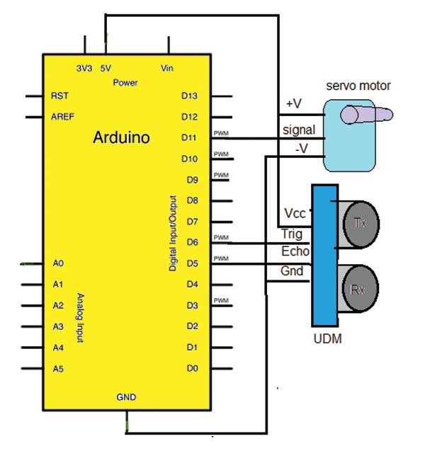
• Ultrasonic sensor (UDM) has 4 wire interface. (1) Vcc (2) Gnd (3) Trig(input) and (4) Echo (output). Vcc is connected to +5 V pin and Gnd is connected to ground pin of arduino board. Trig pin is connected to digital pin 6 and echo pin is connected to digital pin 5.
• Servo motor has 3 wire interface. (1) Vcc (2) Gnd and (3) PWM input (signal). Again Vcc is connected to +5V pin and Gnd is connected to ground pin of arduino board. PWM input is connected to analog output pin 11.
• Arduino board is connected to computer/laptop through USB cable for serial communication as well as to download the program.
Circuit operation
1. The servo motor continuously rotates from 0o to 180o and again back from 180o to 0o in steps of 30o
2. The UDM sensor is mounted on servo motor shaft. So the sensor also rotates from 0o – 180o – 0o continuously.
3. At every angle the trigger pulse is given to UDM and echo signal is received.
4. The received echo pulse duration is converted into distance using formula.
Distance (in cm) = pulse duration / 58*
5. If the any object is within the specified range (< 30 cm = 1 foot) then the distance of object and angle of object is sent to computer.
6. When object is detected its actual angle is read from servo motor and it is sent to computer.
7. Thus the UDM sensor continuously scans 180o circle and detects any object that is within 30 cm limit (actually the UDM sensor can detect objects upto 400 cm but here for demonstration, the range is kept 30 cm only. But one can keep any other range like 100 cm or 200 cm etc)
*Note: The speed of sound is 340 m/s
That means sound signal covers distance of 340 m in 1 sec
Then in 1 us sound travels 1×10⁶/340×100 = 29.41 cm
So in 1 us the sound will travel 29.41 cm. Because we have to consider to-&-fro journey of sound signal, to get exact distance the pulse duration has to be divided by double of 29.41 that is 2×29.41≈58.
Software program
The software program is the soul of the system. Complete functionality of system depends upon the program. It performs following tasks – :
• Rotates servo motor in a step of 30o from 0o to 180o and back to 0o
• Gives trig pulse input to UDM sensor
• Receives echo signal from UDM sensor
• Convert echo pulse duration into distance
• Checks if distance is less than 30 cm
• If distance is less than 30 cm, reads servo motor angle and send it to serial monitor along with object distance
The program is edited and compiled in Arduino IDE and then it is uploaded into internal FLASH of Arduino AVR MCU Atmega328.
Project Source Code
###
//Program to#include <Servo.h> // include header file for servo library
Servo myservo; // create instance of servo class
const int trigPin = 6; // declare UDM trigger pinconst int echoPin = 5; // declare UDM echo pinint radar_angle = 0,actual_radar_angle;void setup(){Serial.begin(9600); // initialize serial communication:pinMode(trigPin, OUTPUT); // trig pin as outputpinMode(echoPin, INPUT); // echo pin as inputmyservo.attach(11); // attach servo motor to pin 11myservo.write(90); // rotate it to 90 deg first}void loop(){long duration,distance_cm;//increase radar angle from 0 to 180 deg in step of 30 degfor (radar_angle = 0; radar_angle <= 180; radar_angle += 30){myservo.write(radar_angle); // rotate motordigitalWrite(trigPin, LOW); // apply trig as 0-1-0delayMicroseconds(2);digitalWrite(trigPin, HIGH);delayMicroseconds(10); // for 10 usdigitalWrite(trigPin, LOW);duration = pulseIn(echoPin, HIGH); // get the pulse duration// calculate the distancedistance_cm = microsecondsToCentimeters(duration);if(distance_cm<30){Serial.print("Object Detected at an angle = "); // print messageactual_radar_angle = myservo.read(); // print motor actual angleSerial.print(actual_radar_angle);Serial.print(" deg and distance = ");Serial.print(distance_cm); // and object distanceSerial.print(" cm");Serial.println();}delay(500); // wait for half second}// now rotate motor reverse and do same as abovefor (radar_angle = 180; radar_angle >=0; radar_angle -= 30){myservo.write(radar_angle);digitalWrite(trigPin, LOW);delayMicroseconds(2);digitalWrite(trigPin, HIGH);delayMicroseconds(10);digitalWrite(trigPin, LOW);duration = pulseIn(echoPin, HIGH);distance_cm = microsecondsToCentimeters(duration);if(distance_cm<30{Serial.print("Object Detected at an angle = ");actual_radar_angle = myservo.read();Serial.print(actual_radar_angle);Serial.print(" deg and distance = ");Serial.print(distance_cm);Serial.print(" cm");Serial.println();}delay(500);}}long microsecondsToCentimeters(long microseconds){return microseconds / 58;}###
Circuit Diagrams
Project Video
Filed Under: Electronic Projects
Filed Under: Electronic Projects

Questions related to this article?
👉Ask and discuss on EDAboard.com and Electro-Tech-Online.com forums.
Tell Us What You Think!!
You must be logged in to post a comment.