This is a project based on Arduino board which can measure the power consumption of the devices. When we connect this wattmeter on to a device which is in operation, the 16*2 LCD displays its power consumption value in Watts. The project uses an Arduino pro mini board whose ADC feature is used along with the concept of Ohm’s law and Voltage Divider circuit to develop this Wattmeter.

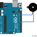
Fig. 1: Prototype of Arduino based Watt Meter
Description
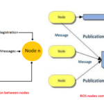
The entire project can be divided into three basic blocks;
1) Power Sensor Unit
2) Processor Unit
3) Display Unit

Fig. 2: Block Diagram of Arduino based Watt Meter
The Power Sensor Unit allows the current to flow through a device whose power consumption needs to be measured. The Sensor Unit produces two voltages, one is the Voltage output from the power supply and another one is a voltage which ranges from 0 to 5V. The difference between these two voltages is proportional to the amount of Current flowing through the Sensor unit.
The Processor Unit can take two input voltages both in the range of 0 to 5V. This unit takes the Sensor Unit’s output as input voltages and uses the ADC to read these voltages. An Algorithm is then applied to calculate the Power consumption of the device. The unit then sends a 4bit data to the Display Unit to display the power consumption in Watts.
The Display Unit takes the 4bit data from the Processor Unit and produces a 16*2 display for the current consumption of the device.
1) Power Sensor Unit
The Power Sensor in this project is a single low valued resistor through which the current flows to the load device. The Voltage across the resistor and the current flow through the resistor are measured to calculate the Power consumption of the device.
In our project we implement resistor ‘R’ in the current flowing path whose resistance value is known. Then we measure the voltage at both the ends of the resistor to calculate the current flow with the help of the following equation.
I = (V2 – V1) / R

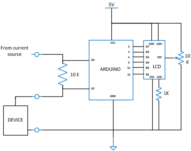
Fig. 3: Circuit Diagram of Power Sensing Circuitry
We have selected a value of R = 10 ohms, now the equation for calculating the power becomes;
I = V2 – V1 / 10
Once we obtain the value of current ‘I’, the power consumed by the device ‘P’ can be calculated using the following equation;
P = V2 * I
2) Processor Unit
The processor unit in this project is the Arduino board and it uses the ADC module to read the output voltages V1 and V2 from the Sensor Unit. In the Arduino board we are using an 8 channel, 10 bit ADC with the reference voltage pin connected to 5 V. The ADC reads the voltage V1, V2 and generates an equivalent value ‘ValueADC‘at the ADC register. From this value the algorithmcalculates the voltages V1 and V2 and then the Power consumption.
Once the values of V1 and V2 are obtained the value of the current flow ‘I’ is calculated using the known values of R = 10 ohms, with the help of equation;
I = (V2 – V1) / 10
The Power consumption is then calculated using the equation;
P = V2 * I
The following piece of code calculates the power and displays it on the LCD.
dc_power = dc_current_I0 * dc_voltage_V1;
lcd.clear();
lcd.setCursor(0, 0);
lcd.print(dc_power);
lcd.print(” mW DC”);
Display Unit & Code Explanation
3) Display Unit
The Display Unit uses a standard 16*2 LCD on which the Arduino displays the Power consumption value. The LCD has been wired in four bit mode to reduce the number of output pins of the Arduino board to be used.

Fig. 4: Image showing LCD Module used for displaying Resistance
Code Description
The code continuously read the ADC channels A0 and A2 one after the other, each time calculating the values of V1 and V2.When both the values of V1 and V2 are obtained, the code then calculates the value of Power consumption of the device and that value is displayed on the 16*2 LCD.
The code running in the Arduino used the library function analogRead() to obtain the ADC value and lcd.print() to display the data on 16*2 LCD.

Fig. 5: Flow Diagram of Arduino Code for Power Measurement
Limitations:
The 10 ohm resistor is a high value compared to 0.05 ohm precision resistor inside a multi-meter. More current flow more voltage get drop across the resistor, and that voltage drop is proportional to value of resistance. For current values above 500mA measurement, create a low resistance by connecting as many resistances in parallel as possible. Since the ADC of Arduinocan read a maximum of 5V only, don’t use a current source with voltage more than 5V.
You may also like:


Project Source Code
###
// include the library code:
#include
// initialize the library with the numbers of the interface pins
LiquidCrystal lcd(12, 11, 5, 4, 3, 2);
int adc_value = 0;
int voltage_peak_value = 0;
float voltage_average_value = 0;
float dc_voltage_V0 = 0;
float ac_voltage_V0 = 0;
float dc_voltage_V1 = 0;
float ac_voltage_V1 = 0;
float dc_current_I0 = 0;
float ac_current_I0 = 0;
float dc_power = 0;
float ac_power = 0;
unsigned long resistance;
unsigned long sample_count = 0;
void setup()
{
// set up the LCD's number of columns and rows:
lcd.begin(16, 2);
// Print a message to the LCD.
lcd.print(" EG LABS ");
pinMode(13, OUTPUT);
}
void loop()
{
// Serial.println("=============================== VOLTAGE ========================================");
voltage_peak_value = 0;
for(sample_count = 0; sample_count < 5000; sample_count ++)
{
adc_value = analogRead(A0);
if(voltage_peak_value < adc_value)
voltage_peak_value = adc_value;
else;
delayMicroseconds(10);
}
dc_voltage_V0 = voltage_peak_value * 0.00488;
ac_voltage_V0 = dc_voltage_V0 / 1.414;
// Serial.println("================================ CURRENT ========================================");
voltage_peak_value = 0;
for(sample_count = 0; sample_count < 5000; sample_count ++)
{
adc_value = analogRead(A2);
if(voltage_peak_value < adc_value)
voltage_peak_value = adc_value;
else;
delayMicroseconds(10);
}
dc_voltage_V1 = voltage_peak_value * 0.00488;
ac_voltage_V1 = dc_voltage_V1 / 1.414;
dc_current_I0 = (dc_voltage_V1 - dc_voltage_V0) * 100;
ac_current_I0 = (ac_voltage_V1 - ac_voltage_V0) * 100;
//================================= POWER =========================================
dc_power = dc_current_I0 * dc_voltage_V1;
ac_power = ac_current_I0 * ac_voltage_V1;
lcd.clear();
lcd.setCursor(0, 0);
lcd.print(dc_power);
lcd.print(" mW");
//=================================================================================
delay(1000);
}
###
Circuit Diagrams
Project Video
Filed Under: Electronic Projects
Filed Under: Electronic Projects

Questions related to this article?
👉Ask and discuss on EDAboard.com and Electro-Tech-Online.com forums.
Tell Us What You Think!!
You must be logged in to post a comment.