In the previous tutorials, we learned about serial communication using the SPI (serial peripheral interface) and seven-segment multiplexing using the MAX7219 IC. We’ve also covered digital I/O, analog input, PWM (pulse width modulation), and all of the serial communication protocols commonly used by embedded controllers (the UART, I2C, and SPI).
This completes the basic coverage of the Arduino platform. With the above-mentioned skillsets, we can now learn about interfacing various sensors, modules, as well as input and output devices with Arduino.
In this tutorial, we’ll learn how to interface a buzzer/beeper with Arduino.
Buzzers & beepers
Buzzers are audio signaling devices that generate sound in the frequency range of 1~7 kHz and, typically, serve as an indicator. This frequency range is within the hearing threshold, which is why a buzzer can usually be heard in noisy environments.
There are many types of buzzers, including piezoelectric, magnetic, electromagnetic, mechanical, and electromechanical buzzers. The piezoelectric and magnetic buzzers are most widely used in the electronics industry.
Buzzers can be designed to operate as a transducer or an indicator. A transducer buzzer has no built-in driving circuit. It can be used to generate tones of various frequencies using an external driving circuit. A transducer buzzer is often actuated by a square wave input, where the sound of the buzzer can be controlled by the frequency of this wave. Several sound frequencies can be played by applying a different square wave input to the buzzer.
The indicator buzzer has a built-in driving circuit that only lets it play a particular frequency or set of frequencies. These types of buzzers can be actuated by applying a DC voltage to their input.
In electronic applications (~12V), the indicator buzzers can be actuated directly from:
- A controller or computer’s digital I/O pin
- A controller or computer’s digital I/O via a transistor or an amplifier circuit
Regardless of the type, a buzzer is always a two-terminal device. One of these terminals is the ground, which should be connected to the common ground of the circuit. The other is the input pin, which should be supplied by DC voltage or a square wave input, depending on its type.
Note: even if a square wave input is applied to an indicator buzzer, it will remain actuated for TON and will remain muted for TOFF.
Piezoelectric buzzers
Piezoelectric buzzers have a piezo-electric ceramic. The ceramic is attached to a metal plate and will shrink and stretch diametrically when an alternating current is applied to it. When the ceramic shrinks and stretches rapidly, it produces vibrations of the same frequency as the attached metal plate. The buzzer will sound the same frequency.
The piezo buzzers have a wide operating voltage that ranges from 3 to 250V. Most of the piezo buzzers that are used in electronic circuits have an operating voltage between 3 and 12V, with high sound-pressure levels. They also have a low current consumption (~30 mA). Piezo buzzers offer a large footprint and are typically used in cost-sensitive electronic applications.
Magnetic buzzers
Magnetic buzzers have a ferromagnetic disc that’s attached to a pole. Magnets are attached around the pole and a coil below the ferromagnetic disc act as an electromagnet. When a current is supplied to the coil, the disc pulls toward the coil. If there’s no current, the disc remains in its rest position.
The vibrations of the disc are controlled by a weight that’s above it. When an oscillating signal is applied to the coil, the electromagnetic field generated from it also fluctuates, causing vibrations in the ferromagnetic disk. The buzzer produces the same frequency of sound like the one applied by the oscillating signal.
Magnetic buzzers have a narrow operating voltage that ranges between 1 to 16V. These buzzers produce lower-rated frequencies, with low sound-pressure levels. However, they have a slightly greater current consumption (up to 100 mA) compared to the piezo buzzers. Magnetic buzzers offer a small footprint and are, typically, used in high-end consumer applications.
The applications of a buzzer
Buzzers can generate various sounds, such as clicking, beeping, ringing, chiming, and that of a siren. They can be used as an alarm, a warning, or as an indicator (such as the buzzer to indicate the end of classroom time in high school or the start of a sporting event).
Buzzers are also found in alarm devices (such as alarm clocks or fire alarms), timer devices, electronic metronomes, annunciator panels, computer peripherals (motherboards, keyboards, and a mouse), as well as in many consumer electronics applications. Learn about buzzers in detail from here.
The tone() function
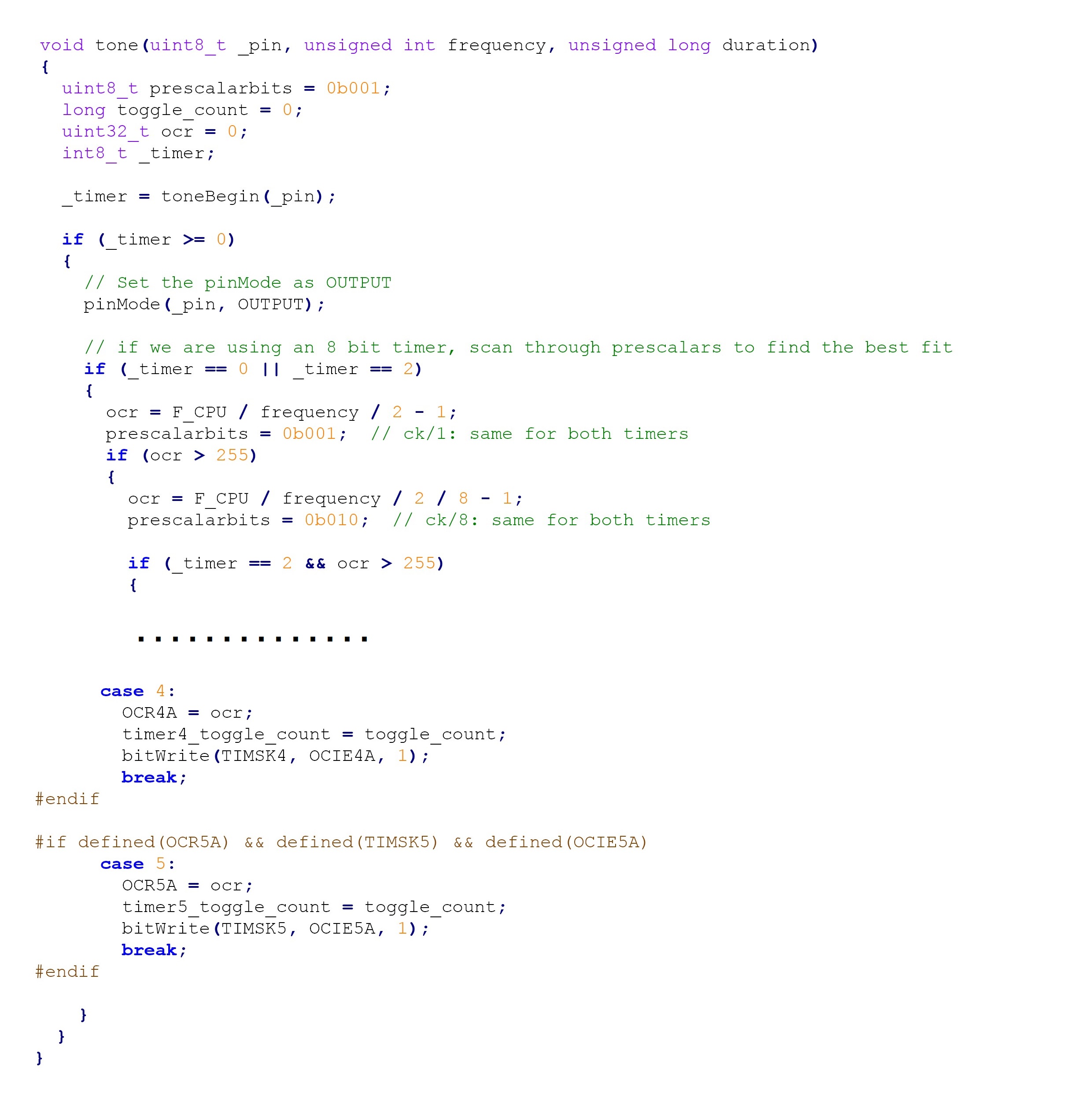
Arduino provides a function tone() that can be used to produce the square wave output from a digital I/O pin. This function is declared in the Arduino.h file and defined in the Tone.cpp file.
The tone() function is one of the basic, built-in Arduino functions such as the pinMode(), digitalWrite(), digitalRead(), analogRead(), or analogWrite(), and so on. Both the Arduino.h and Tone.cpp files are included in Arduino’s core libraries and can be inspected from the Arduino\hardware\arduino\avr\cores\arduino folder.
The tone() function is used to generate the square wave input at the digital I/O pin. Therefore, it can be used to actuate a buzzer. It has this syntax:
void tone(pin, frequency, duration = 0)
It also takes three parameters:
1. The digital I/O pin, where the square wave has to be generated
2. The frequency of the square wave in Hertz
3. The duration in milliseconds, where the square wave has to be generated. This third parameter is optional.
Here’s a valid example of this method:
tone(9, 1000); // 1KHz Square Wave from pin 9
This function uses one of the built-in timers from Arduino’s AVR controller to generate the square wave signal. As such, the delay() function will have no effect on it. To stop the square wave output, the duration must be passed as a parameter — assuming the output is for a fixed period of time. Otherwise, the noTone() function should be called.
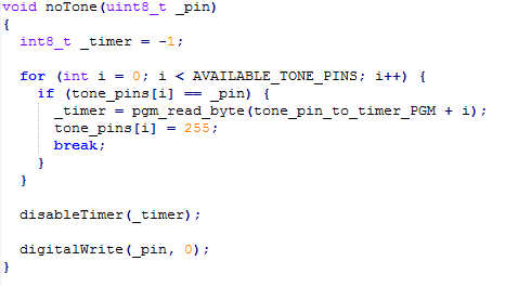
The noTone() function
This function disables the square wave output from Arduino’s pin. It has this syntax:
noTone(pin)
It takes only one parameter, which is the digital I/O pin where the tone has to be disabled. This is a valid example:
noTone(9);
It will stop the tone at the given pin, disable the timer, and set the given pin to LOW.
Interfacing the buzzer with Arduino
It’s quite simple to interface a buzzer/beeper with Arduino. All buzzers have two terminals and one is marked by a positive sign. This is the input terminal.
Be sure to check the specifications of the buzzer before use to ensure it can be driven directly by a 5V digital I/O pin. It may require a higher voltage or an additional transistor circuitry. Most buzzers designed for electronics applications can be directly actuated by 5V and 3V3 pins.
The positive terminal of the buzzer should be connected directly to Arduino’s digital I/O or through a transistor circuit. Keep the other terminal grounded.
It’s also important to place a current-limiting resistor in series with the buzzer. This is because the buzzer sinks current from the controller pin and can potentially damage it via a leak or surge. So, a small-value resistor must be placed in series with the buzzer and the controller pin to avoid any possible damage — and even if the buzzer’s specific part number is unknown.
Nearly all buzzer modules have a series resistor. If the part number of the buzzer transducer is known, the value of the current limiting resistance can be found from the datasheet.
So, let’s suppose that a buzzer has an operating voltage of 5V, a maximum current rating of 40 mA, and a coil resistance of 47 Ω. To be safe in this case, we’d allow the current driving the buzzer to be maintained at 20 mA. This means that using a 5V operating voltage and a 20-mA current, the resistance across the buzzer should be 250 Ω (R = V/I). And, as the coil resistance is given 47 Ω, the current limiting resistor should be at least 200 Ω.
Generating a beep
A buzzer’s beep sounds can be generated by periodically actuating and deactivating the buzzer. In Arduino, this can be done by calling the tone() function, with a given duration, and then calling the delay() function for a greater duration. Otherwise, the tone() and noTone() functions can be called alternatively, with some delays.
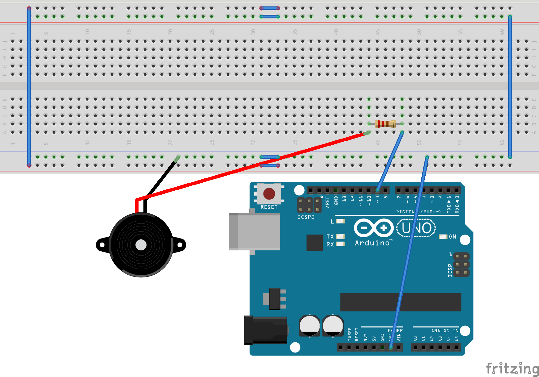
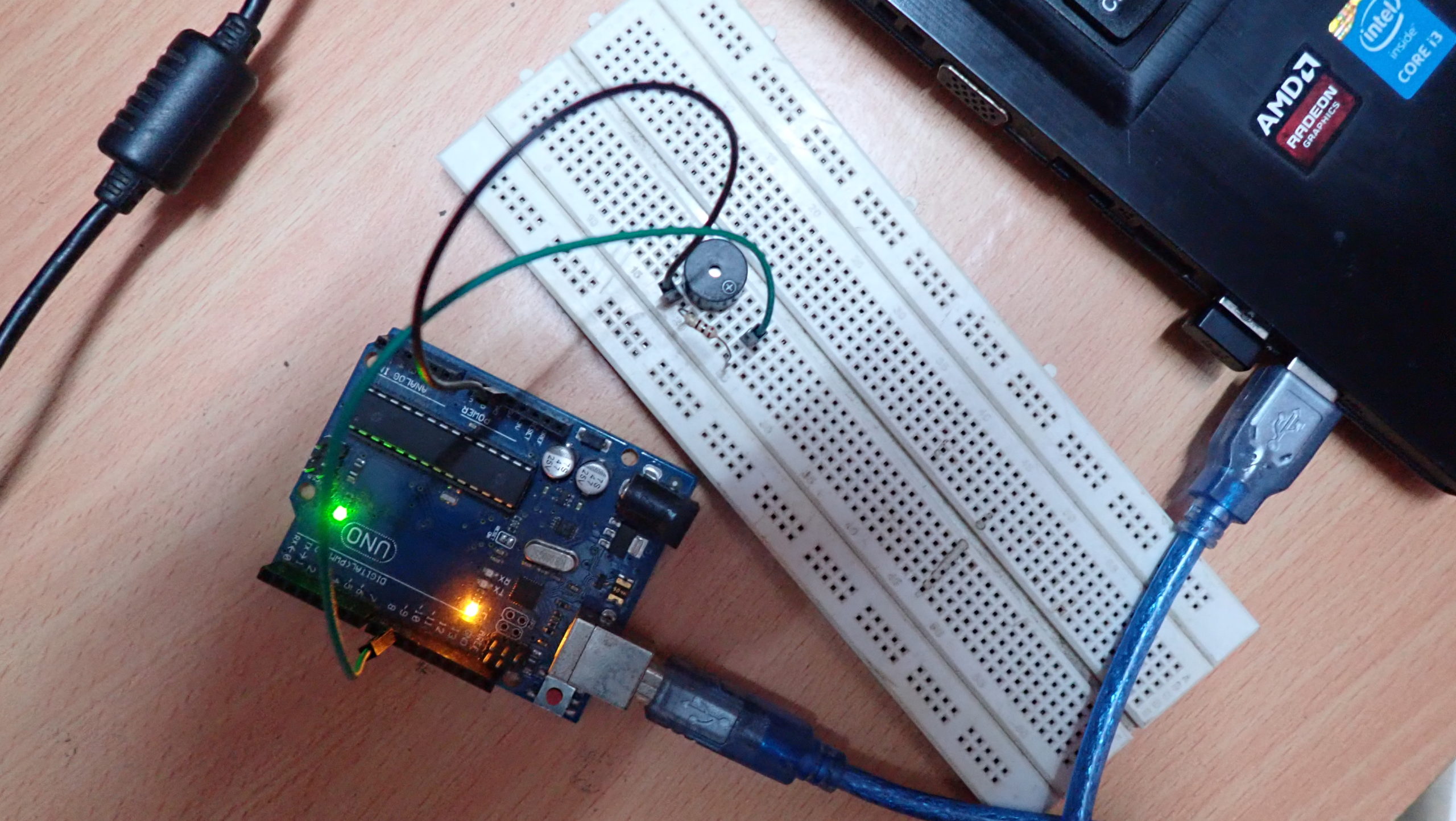
Recipe: Interfacing a buzzer with Arduino
In this recipe, we will interface a buzzer with Arduino and generate a beep sound from it.
Components required
1. Arduino Uno x1
2. Buzzer x1
3. Resistor 100Ω x1
4. Breadboard x1
5. Jumper/connecting wires
Circuit connections
- Connect Arduino UNO’s pin 9 to one of the terminals of the 100Ω resistor
- Connect the other terminal of the resistor to the positive terminal of the buzzer
- Connect the other terminal of the buzzer to the ground
Arduino sketch
const int buzzer = 9;
void setup(){
pinMode(buzzer, OUTPUT);
}
void loop()
{
tone(buzzer, 1000); // 1KHz
delay(1000);
noTone(buzzer); // Stop
delay(1000);
}
Alternatively, this sketch can be used:
const int buzzer = 9;
void setup(){
pinMode(buzzer, OUTPUT);
}
void loop()
{
tone(buzzer, 1000, 1000); // 1KHz
delay(2000);
}
How the circuit works
A buzzer transducer is interfaced with the Arduino UNO. When the square wave is input to the positive terminal of the buzzer, it will generate a sound of the same frequency.
A square wave of 1 kHz is applied to the buzzer’s terminal. The square wave is applied and deactivated using the tone() and noTone() functions. This produces a beep sound from the buzzer.
Alternatively, the tone() function can be called with a given duration, and the delay() function (with a greater duration) can be called to create the same sound effect.
The higher the frequency of the input signal, the higher pitch of the buzzer sound.
Programming guide
The Arduino sketch begins by declaring a variable to store the pin number with which the buzzer is interfaced.
In the setup() function, this pin is set as the digital output by using the pinMode() function. In the loop() function, the tone() and noTone() functions are called on for the same pin so as to generate the buzzer sound.
Alternatively, it’s possible to call the tone() function with a given duration and the delay() function, with greater duration, to create the same sound effect.
As the loop() keeps iterating, the buzzer periodically beeps.
xf
In the next tutorial, we’ll learn how to interface a matrix keypad with Arduino.
Filed Under: Arduino, Microcontroller Projects

Questions related to this article?
👉Ask and discuss on Electro-Tech-Online.com and EDAboard.com forums.
Tell Us What You Think!!
You must be logged in to post a comment.