Engineers Garage

  • Projects and Tutorials
    • Electronic Projects
      • 8051
      • Arduino
      • ARM
      • AVR
      • PIC
      • Raspberry pi
      • STM32
    • Tutorials
    • Circuit Design
    • Project Videos
    • Components
  • Articles
    • Tech Articles
    • Insight
    • Invention Stories
    • How to
    • What Is
  • News
    • Electronic Products News
    • DIY Reviews
    • Guest Post
  • Forums
    • EDABoard.com
    • Electro-Tech-Online
    • EG Forum Archive
  • Digi-Key Store
    • Cables, Wires
    • Connectors, Interconnect
    • Discrete
    • Electromechanical
    • Embedded Computers
    • Enclosures, Hardware, Office
    • Integrated Circuits (ICs)
    • Isolators
    • LED/Optoelectronics
    • Passive
    • Power, Circuit Protection
    • Programmers
    • RF, Wireless
    • Semiconductors
    • Sensors, Transducers
    • Test Products
    • Tools
  • EE Resources
    • DesignFast
    • LEAP Awards
    • Oscilloscope Product Finder
    • White Papers
    • Webinars
  • EE Learning Center
  • Women in Engineering

Arduino color sensor used in hospitals

By Usman ali Butt

This tutorial is about interfacing color sensors with Arduino. We will design an autonomous patient movement system in hospitals. The color sensor which I am going to use in the project is Adafruit TCS34725. Adafruit provided predefined Arduino libraries for this sensor. It consumes 3.3v to 5v and outputs data on the I2C interface.

Color bands are stuck on the hospital floor. The bands start from the hospital entrance and lead to a specific department (emergency etc.) or ward.

The idea is to make a DIY autonomous robot (wheelchair, bed, etc.) that can take a patient from the desired ward entrance. Upon entrance, the patient can be laid on the bed and placed on the color strip, and taken to the ward.

To achieve the above functionally, we have to overcome few constraints:

  • How to turn?
  • What if the sensor goes out off the strip?

There are many ways in which the above task can be achieved using a color sensor.

Using multiple color sensors:

Multiple color sensors apart from each other cover a big area, so if one sensor moves out of the strip, others can cover the strip.

Single color sensor:

A single-color sensor, when it goes out of the strip, is impossible to retract. It needs the wheelchair motors to reverse.

Turning

Turns are hard to predict using color sensors. One way to take a turn is reducing speed and first moving a little left and see if we are in color range. If not moving a little right and repeat the process until we are aligned again.

Another way is to stick a small piece of another color strip on the main strip’s sides.

On the sides of the main red strip, small strips are also attached. When the sensor reaches the blue small strip it turns slightly right, and when orange, it turns slightly left. In this way, we can even take sharp turns.

Ultrasonic sensor

If any obstacle is ahead, we want our platform to stop. The best solution is to attach an ultrasonic sensor in front of the platform so if it detects any obstacle, it immediately stops.

Our system will behave like a rover. Four dc motors are driving platforms. Motors moving in the direction of the color strip. The color sensor takes control of motor movement decisions.

Circuit diagram

Four dc motors are connected to digital pins (10,11,12,13) of Arduino. An external motor driver drives motors. External motor driver has voltage and current regulator, which fulfills the power requirement of motors.  Flywheel diodes on the motor driver protect Arduino core from back EMF.

The color sensor is attached to analog pins (A4 and A5) of Arduino. The sensor is powered through Arduino power output.

Project code

First, I imported the Adafruit library for the color sensor and I2C library in Arduino sketch. Then color sensor processing speed is defined. In 700ms, we will get a new reading from the sensor. The speed variable controls the motor speed. Where 0 means motor off and 255 represents max speed. In the setup function, digital pins controlling motors and color sensor is initialized.

In the main function, colors are grabbed—color sensors output color in RGB (Red, Green, and Blue) values. We have to build a system which knows the exact color manually. Each R, B, and G is 8-bit color. So total colors represented are 256*256*256=16777216.

To know exactly each color, we must train our system. Represent RBG vectors in Arduino and compare them with the sensor output. It’s a tedious task, and above all, we can’t represent all the colors 16777216. The range of color codes can be grouped, and decisions can be made based on groups.

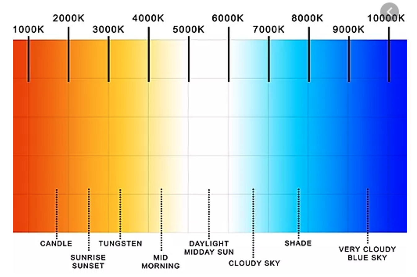
In the above code, I am making decisions based on color temperature. Adafruit color sensors can also monitor the temperature of the color. Each color has a different temperature.

The above diagram shows the temperature of the colors. In Arduino sketch temperature of color is continuously monitored. If any change is found, adjustments are made by moving the platform left and right.

Note: The above project prototype requires a lot of training. Although much better solutions are available in the market. We learned how we could achieve this task using a color sensor.

Let’s DIY the project: Where to purchase parts? 

Adafruit color sensor: Mouser
Arduino: Mouser electronics
Vehicle development platform: DigiKey
Motor driver: Mouser electronics

You may also like:


  • Wireless distance measurement using ultrasonic sensor

  • Bistatic ultrasound radar system

  • Ultrasound Imaging or Ultrasonography

Filed Under: Arduino, Microcontroller Projects


Questions related to this article?
👉Ask and discuss on Electro-Tech-Online.com and EDAboard.com forums.


Tell Us What You Think!! Cancel reply

You must be logged in to post a comment.

HAVE A QUESTION?

Have a technical question about an article or other engineering questions? Check out our engineering forums EDABoard.com and Electro-Tech-Online.com where you can get those questions asked and answered by your peers!


Featured Tutorials

  • Designing Gate Driver Circuit and Switching Mechanism for Modified Sine Wave Inverter – (Part 9/17)
  • Completing Modified Sine Wave Inverter Design with Full Bridge Circuit and Step Up Transformer – (Part 10/17)
  • Designing an Offline UPS – Part (12 /17)
  • How to reduce Switching Time of a Relay – (Part 15/17)
  • Testing MOSFET – (Part 16/17)
  • Driving High Side MOSFET using Bootstrap Circuitry – (Part 17/17)

Stay Up To Date

Newsletter Signup

Sign up and receive our weekly newsletter for latest Tech articles, Electronics Projects, Tutorial series and other insightful tech content.

EE Training Center Classrooms

EE Classrooms

Recent Articles

  • Designing Gate Driver Circuit and Switching Mechanism for Modified Sine Wave Inverter – (Part 9/17)
  • Completing Modified Sine Wave Inverter Design with Full Bridge Circuit and Step Up Transformer – (Part 10/17)
  • Designing an Offline UPS – Part (12 /17)
  • How to reduce Switching Time of a Relay – (Part 15/17)
  • Testing MOSFET – (Part 16/17)

Most Popular

5G 555 timer circuit 8051 ai Arduino atmega16 automotive avr dc motor display Electronic Part Electronic Parts Fujitsu ic infineontechnologies integratedcircuit Intel IoT ir lcd ldr led maximintegratedproducts microchip microchiptechnology Microchip Technology microcontroller microcontrollers mosfet motor powermanagement Raspberry Pi remote renesaselectronics Research robot samsung semiconductor sensor software STMicroelectronics switch Technology vishayintertechnology wireless

RSS EDABOARD.com Discussions

  • Please help to identify the signal input port on board
  • Hotplugging UART
  • RF switch selection
  • sensitivity in filters and number of bits of system
  • MDO4104-6 Front Panel Not Working

RSS Electro-Tech-Online.com Discussions

  • software PWM
  • Combination of Wires of two DC motor giving Output current.
  • Passthrough charging-simple but impossible to achieve?
  • geared motor to revolve oval platform
  • None existant errors (MPLAB X)
Engineers Garage
  • Analog IC TIps
  • Connector Tips
  • DesignFast
  • EDABoard Forums
  • EE World Online
  • Electro-Tech-Online Forums
  • Microcontroller Tips
  • Power Electronic Tips
  • Sensor Tips
  • Test and Measurement Tips
  • 5G Technology World
  • About Us
  • Contact Us
  • Advertise

Copyright © 2022 WTWH Media LLC. All Rights Reserved. The material on this site may not be reproduced, distributed, transmitted, cached or otherwise used, except with the prior written permission of WTWH Media
Privacy Policy | Advertising | About Us

Search Engineers Garage

  • Projects and Tutorials
    • Electronic Projects
      • 8051
      • Arduino
      • ARM
      • AVR
      • PIC
      • Raspberry pi
      • STM32
    • Tutorials
    • Circuit Design
    • Project Videos
    • Components
  • Articles
    • Tech Articles
    • Insight
    • Invention Stories
    • How to
    • What Is
  • News
    • Electronic Products News
    • DIY Reviews
    • Guest Post
  • Forums
    • EDABoard.com
    • Electro-Tech-Online
    • EG Forum Archive
  • Digi-Key Store
    • Cables, Wires
    • Connectors, Interconnect
    • Discrete
    • Electromechanical
    • Embedded Computers
    • Enclosures, Hardware, Office
    • Integrated Circuits (ICs)
    • Isolators
    • LED/Optoelectronics
    • Passive
    • Power, Circuit Protection
    • Programmers
    • RF, Wireless
    • Semiconductors
    • Sensors, Transducers
    • Test Products
    • Tools
  • EE Resources
    • DesignFast
    • LEAP Awards
    • Oscilloscope Product Finder
    • White Papers
    • Webinars
  • EE Learning Center
  • Women in Engineering