A majority of middle-aged people suffer from health issues like asthma and breathing problems, particularly in cities. Air pollution is the major cause of it. In this project, we have designed a portable device that detects different air pollution metrics and displays them on a small OLED screen. People with respiratory issues can use the device to monitor pollution-related metrics and avoid hazardous places. The concept of this device can be integrated into consumer devices like a smartwatch or fitness watch.
In this project, the device is prototyped on Arduino. There are three air pollution metrics – CO2 level, smoke, and dust – that are measured using the device. The CO2 level, smoke particles, and dust density are measured using MQ-135, MQ-2, and GP2Y1010AU0F optical dust sensors. All the metrics are displayed on a 128×64 SSD1306 OLED display.
Components required
- Arduino UNO x1
- MQ-2 Sensor x1
- MQ-135 Sensor x1
- GP2Y1010AU0F optical dust sensor x1
- Resistor 150Ω x1
- SSD1306 OLED Display x1
- Breadboard x1
- Connecting Wires/Jumper Wires
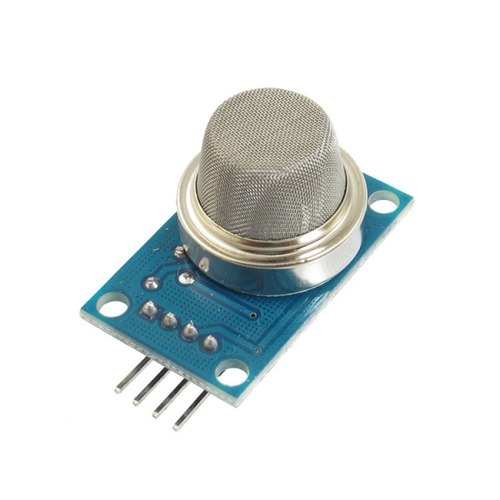
MQ-135 sensor
MQ-135 is an air-quality sensor. It can be used to detect CO2, Nitrogen Oxide, Benzene, NH3, smoke, and alcohol. The load resistance of the sensor can be adjusted to detect a particular gas, smoke, or alcohol. In this project, the MQ-135 sensor is used to detect the CO2 level of the surrounding air. For this, the load resistance in the sensor circuit is adjusted to 22KΩ.
For measurement of air quality, the MQ-135 sensor needs to be pre-heat in clean air. After preheating for 24 hours, the value of R0 can be determined. MQ-135 air quality sensor has four pins – VCC, GND, Dout, and Aout. For preheating the sensor, connect VCC to Arduino’s 5V output, GND to Arduino’s ground pin, and Aout to any analog input pin of Arduino, like A4 in this project. These circuit connections are demonstrated below.
Load the Arduino Sketch-1 to the board and leave it for 24 hours. Then, check the value of R0 from the serial monitor and disassemble the circuit. While building this project, the value of R0 was found to be 929.15Ω.
Arduino Sketch 1 (for preheating MQ-135)
#include “MQ135.h”
void setup (){
Serial.begin (9600);
}
void loop() {
MQ135 gasSensor = MQ135(A4);
float rzero = gasSensor.getRZero();
Serial.println (rzero);
delay(1000);
}
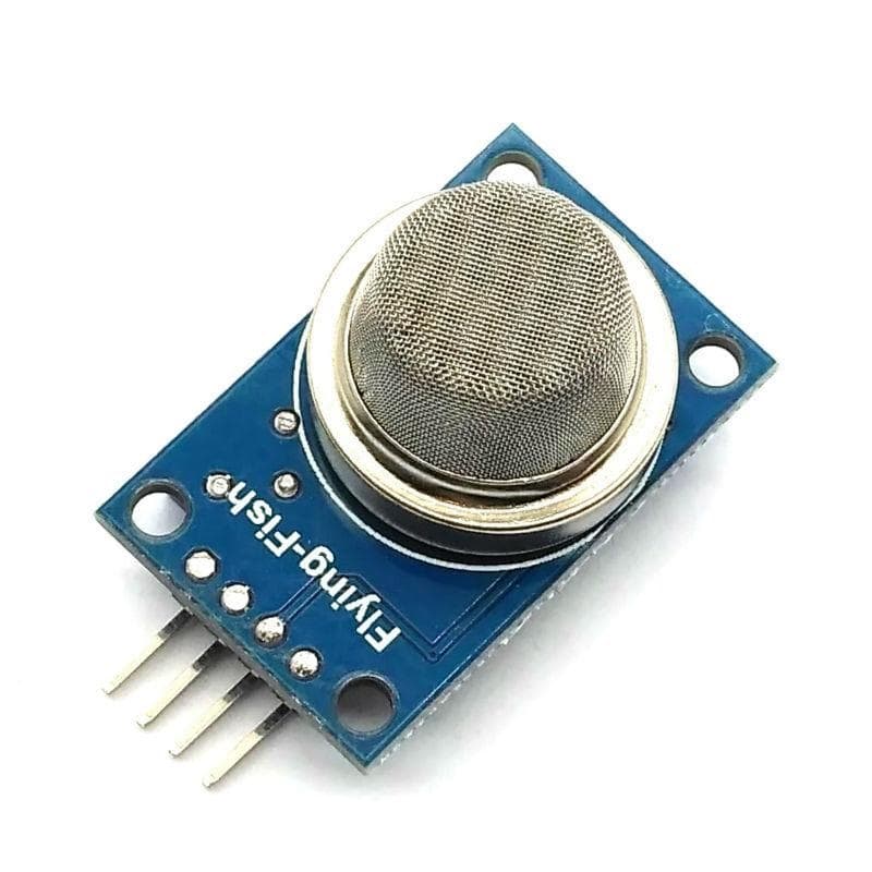
MQ-2 sensor
MQ-2 is also a gas sensor. It can be used to detect LPG, alcohol, hydrogen, methane, propane, and carbon monoxide concentrations in between 200 PPM to 1000 PPM. It is a Metal Oxide Semiconductor (MOS) sensor. It works by changing its resistance when the gas comes in contact with it. A voltage divider circuit detects the change in resistance. The sensor operates on 5V DC and consumes 800 mW power. The sensor has four pins – VCC, GND, D0, and A0. The VCC should be connected to Arduino’s 5V output and GND to Arduino’s ground pin. The D0 pin can be connected to any GPIO. It can be calibrated to provide a LOW output for a threshold level of gas concentration set by a potentiometer in the MQ-2 sensor circuit. The A0 can be connected to any analog input pin of Arduino and provides the value of gas concentration in parts per million (PPM) as a voltage reading. The 10-bit analog reading by Arduino is directly proportional to the gas concentration in PPM.
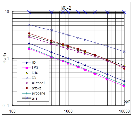
In this project, MQ-2 is used to detect smoke particles. The sensor module used in this project has a load resistance of 20K and is calibrated to output a voltage proportional to smoke level directly. According to the following graph, a bare MQ-2 sensor can be calibrated to detect different gases using a sensing resistance to zero resistance ratio.
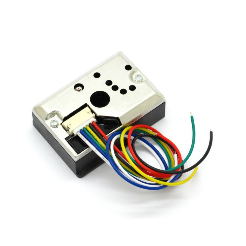
GP2Y1010AU0F optical dust sensor
The GP2Y1010AU0F optical dust sensor is used to sense the dust density in the air. It consists of an IR diode and a photosensor that are assembled diagonally across an air inlet. When air containing dust particles enters the inlet, the dust particles scatter the IR radiations from the diode towards the photosensor. Greater is the dust density, more IR light is scattered, and greater is the output voltage of the photosensor. The GP2Y1010AU0F sensor can detect dust particles as small as 0.5um and dust density up to 0.580 mg/m3.
The GP2Y1010AU0F optical dust sensor has a six-pin connector with the following pin configuration.
SSD1306 OLED display
SSD1306 is a popular OLED display. It is a single-chip CMOS OLED/PLED driver. It can manage a 128×64 dot-matrix graphic display. It is designed to control common-cathode OLED panels. The chip has several built-in features like 256-step brightness control, display RAM, oscillator, and contrast control. These built-in features reduce the required external components and make the chip ready to use with any OLED screen of compatible resolution.
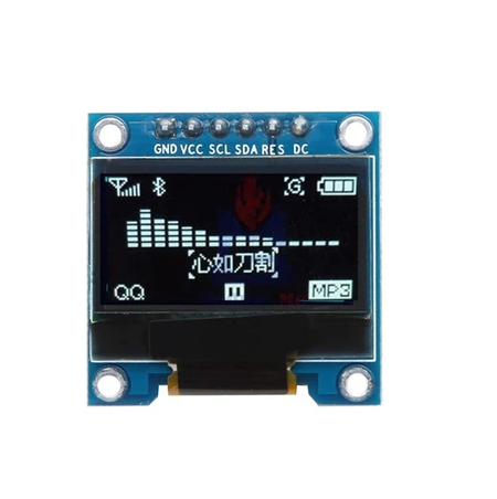
In this project, we are using a 0.96″ OLED display having SSD1306 controller IC. The module has a Yellow-Blue screen with 128×64 screen resolution. The module used here has a 7-pin interface, allowing interfacing the module with Arduino using 3-wire SPI, 4-wire SPI, and I2C interface. The 4-wire SPI interface is the default interfacing option in the 7-pin module. The 7-pin OLED display has the following pin configuration.
Circuit connections
To design this portable pollution monitor, MQ-135, MQ-2, GP2Y1010AU0F optical dust sensor, and SSD1306 OLED display are interfaced with the Arduino UNO.
In this project, a 7-pin SSD1306 OLED module is interfaced with Arduino UNO. The module is connected to the Arduino as follows.
For interfacing GP2Y1010AU0F optical dust sensor with Arduino UNO, make the connections summarized in the table below.
For interfacing MQ2 sensor, connect VCC to Arduino’s 5V out, GND to Arduino’s Ground pin, and Aout to Arduino’s analog input pin A2. For interfacing, the MQ135 sensor connects VCC to Arduino’s 5V out, GND to Arduino’s Ground pin, and Aout to Arduino’s analog input pin A1.
Arduino Sketch
How it works
The device designed in this project detects air quality by measuring CO2 level, smoke, and dust density. It displays the measured metrics on the 128*64 SSD1306 OLED display. For measuring air quality, the MQ-135 sensor is used. The sensor is preheated for 24 hours to obtain the R0 value. The header file uses the value of R0 in the MQ-135 library. Once the actual R0 value is obtained, it is replaced with the default values in the MQ135.h file. The MQ135 library can be downloaded from this link. With a load resistance of 22KΩ, the MQ-135 sensor can be used to measure the concentration of CO2 in the air. The sensor is connected to Arduino’s A1 pin. The concentration of CO2 in the air is obtained using the getPPM() function of the MQ135 library.
Sharp’s GP2Y1010AU0F optical dust sensor is useful in detecting fine particles like cigarette smoke and dust particles in the air. The dust sensor measures dust density in mg/m3. Simultaneously, the dust density is also measured by the circuit.
At the same time, the MQ2 sensor is used to measure smoke particles. The density of smoke particles is measured in a range from 200 PPM to 1000 PPM. The analog reading from the sensor is directly proportional to smoke density in PPM.
When the device is powered on, it starts with displaying the logo of EEWORLDONLINE on the OLED display. Immediately after that, it starts reading values from all three sensors and displays the values on the OLED display. The values are updated every second.
Programming guide
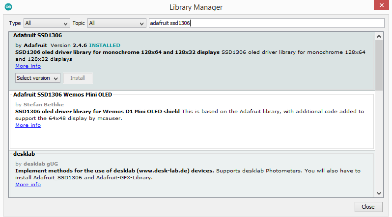
The Arduino sketch begins with importing libraries for SPI communication and libraries required for SSD1306 OLED. The library for interfacing SSD1306 with Arduino is available from Adafruit. To find it navigate to library manager of Arduino IDE, Sketch -> Include Library -> Manage Libraries. Search for SSD1306 and select the latest version of the Adafruit SSD1306 library. It will also download the GFX library as one dependency.
The declaration of SSD1306 specific variables follows the inclusion of libraries for SSD1306. These variables store the SSD1306 specific constant values and pin assignment. A bitmap object is stored in the Arduino’s PROGMEM to store the EEWORLDONLINE’s logo.
This is followed by the definition of RLoad and RZero constants for the MQ-135 sensor and the inclusion of the MQ-135 library. This MQ-135 library can be downloaded as a Zip file from this link and can be imported by navigating to Sketch-> Include Library -> add .Zip library. The variables are declared for storing sensor values and pin assignment for dust sensor, MQ-135, and MQ-2 sensor.
A function drawbm() is defined to show the EEWORLDONLINE logo on the SSD1306 OLED display. In the setup() function, the baud rate for serial communication is set to 9600 as all the pollution metrics are also communicated to the serial port for observation. The SSD1306 OLED display is initiated by calling display. Begin () function, and the EEWORLDONLINE logo is displayed on the screen. The MQ135 sensor pin is set as input, and the pin connecting to the LED of the dust sensor is set as output. The analog pin-connected MQ-2 sensor is also set as input.
In the loop() function, first of all, the dust level is calculated. The IR diode is turned ON for 280 microseconds for measuring dust level, and the output voltage from the photosensor is read. The reading output voltage from the dust sensor takes around 40 to 50 microseconds, so a delay of 40 microseconds is provided. According to the datasheet of GP2Y1010AU0F, the IR diode is pulsed every 10 milliseconds, so still, 9.68 milliseconds are left. The dust level is calculated using the following equations and printed to the Serial Monitor.
calcVoltage = voMeasured*(5.0/1024);
dustDensity = 0.17*calcVoltage-0.1;
Then, the analog reading from the MQ-135 sensor is obtained, and the value of CO2 concentration in PPM is calculated. Similarly, the analog reading from the MQ-2 sensor is obtained, and the value of smoke density in PPM is directly obtained. All the pollution metrics are communicated to the serial monitor as well as displayed on the OLED screen.
It should be noted that for displaying string values to OLED display, display.write() function is used while to display sensor values (numerical values), display.the print() method is used. A delay of 1000 milliseconds is provided to repeat updating of metrics every second.
Result
You may also like:
Filed Under: Arduino, Arduino., Electronic Projects, Sensors, Tutorials, Video







Questions related to this article?
👉Ask and discuss on EDAboard.com and Electro-Tech-Online.com forums.
Tell Us What You Think!!
You must be logged in to post a comment.