Electronic door locks are safer than conventional door locks. There is no possibility of lock picking in such door locks as the entire mechanism is electronic. Such door locks have an underlying embedded access control system which is generally impenetrable. Several access control systems are used in electronic door locks. The most common access control systems used in electronic locks are PIN (Personal Identification Number), fingerprint, and RFID.
The fingerprint access control systems are preferred only for high security or personal security solutions, are highly personalized, and are costly. The PIN and RFID are cost-effective solutions applicable to public access systems like hotel rooms, classrooms, and offices. Of these two, RFID access control systems come with higher security and offer wider applications. For example, RFID solutions can be used simultaneously for access control as well as attendance in school/college classrooms.
In this project, we are designing an RFID door lock system and will explore how the locking mechanism can be built in different ways.
Components required
- Arduino UNO/Arduino Mega x1
- RC522 RFID Reader x1
- MFRC522 RFID cards/tags x2
- SSD1306 OLED display x1
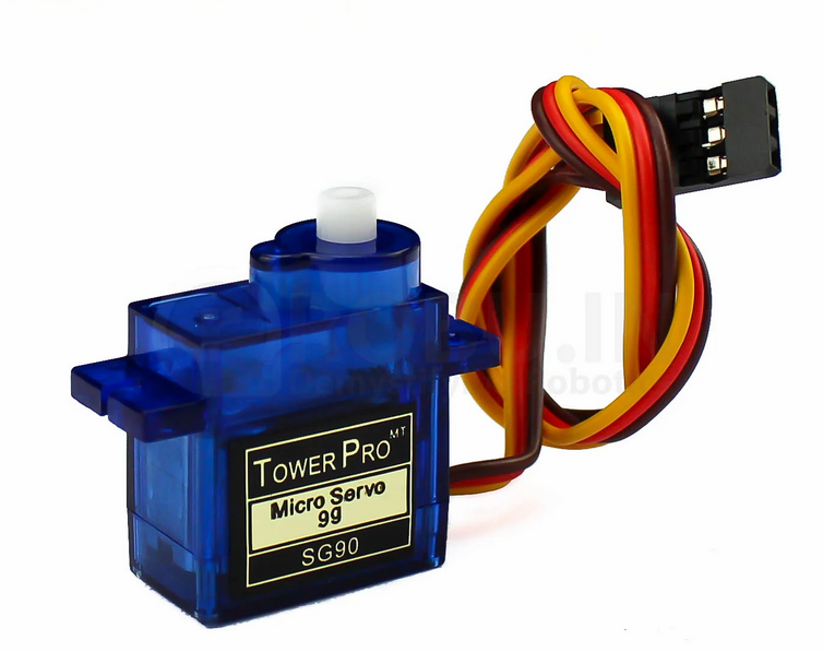
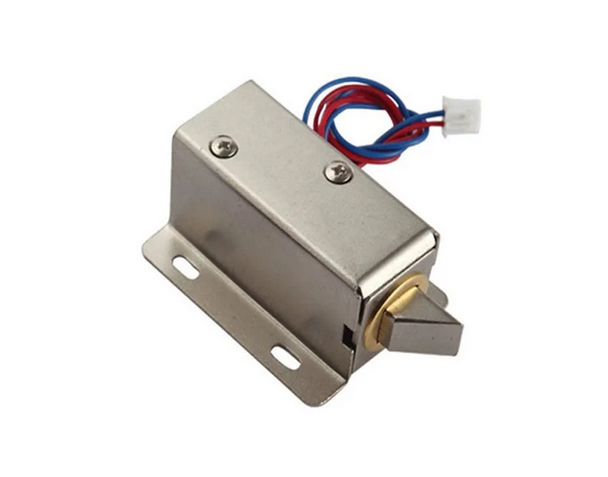
- Relay module & solenoid lock or Servo motor x1
- Connecting wires/jumper wires
Circuit connections
The door lock system consists of two critical circuits – the access control system and a locking mechanism. For the access control system here, an RFID is used. This door lock uses an RC522 RFID reader to read MIFARE and NTAG compatible RFID cards. Each lock passes access to only one RFID card, so all other cards are denied access. The system can also be programmed to provide additional access to a master card, which may be used instead of a lost card. The user interface is designed using an SSD1306 OLED display. Therefore, the complete access control system is designed by interfacing the RC522 RFID reader and SSD1306 OLED display with Arduino UNO.
The RC522 RFID reader is interfaced with Arduino using SPI protocol. The following circuit connections are made for interfacing the RFID reader with Arduino UNO. To learn more about reading RFID cards using RC522, check out this link.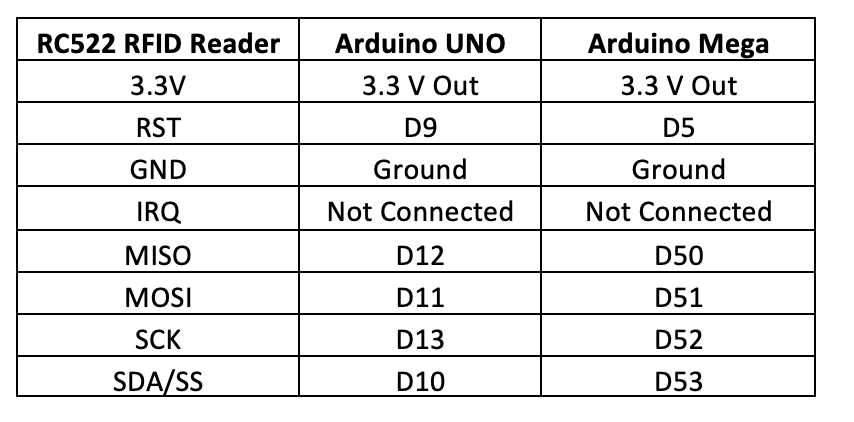
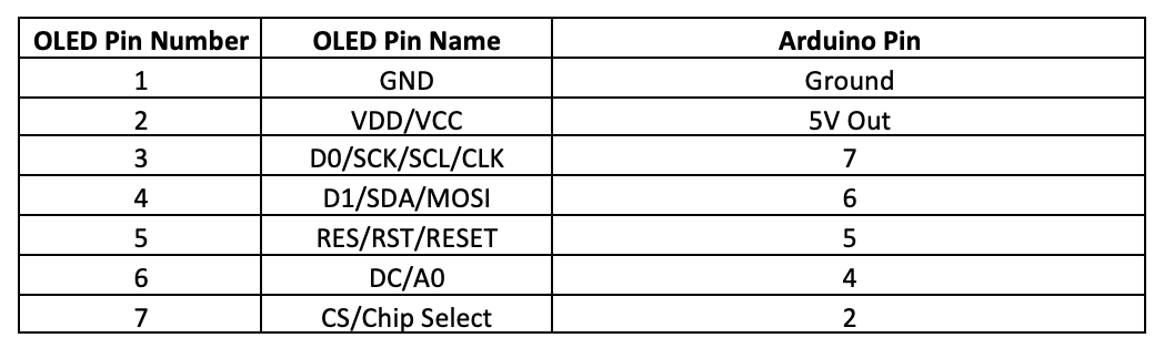
The SSD1306 OLED is interfaced with Arduino using the I2C protocol. To learn more about interfacing SSD1306 OLED display with Arduino using serial I2C, check out this link. For interfacing SSD1306 with Arduino, the following circuit connections are made.
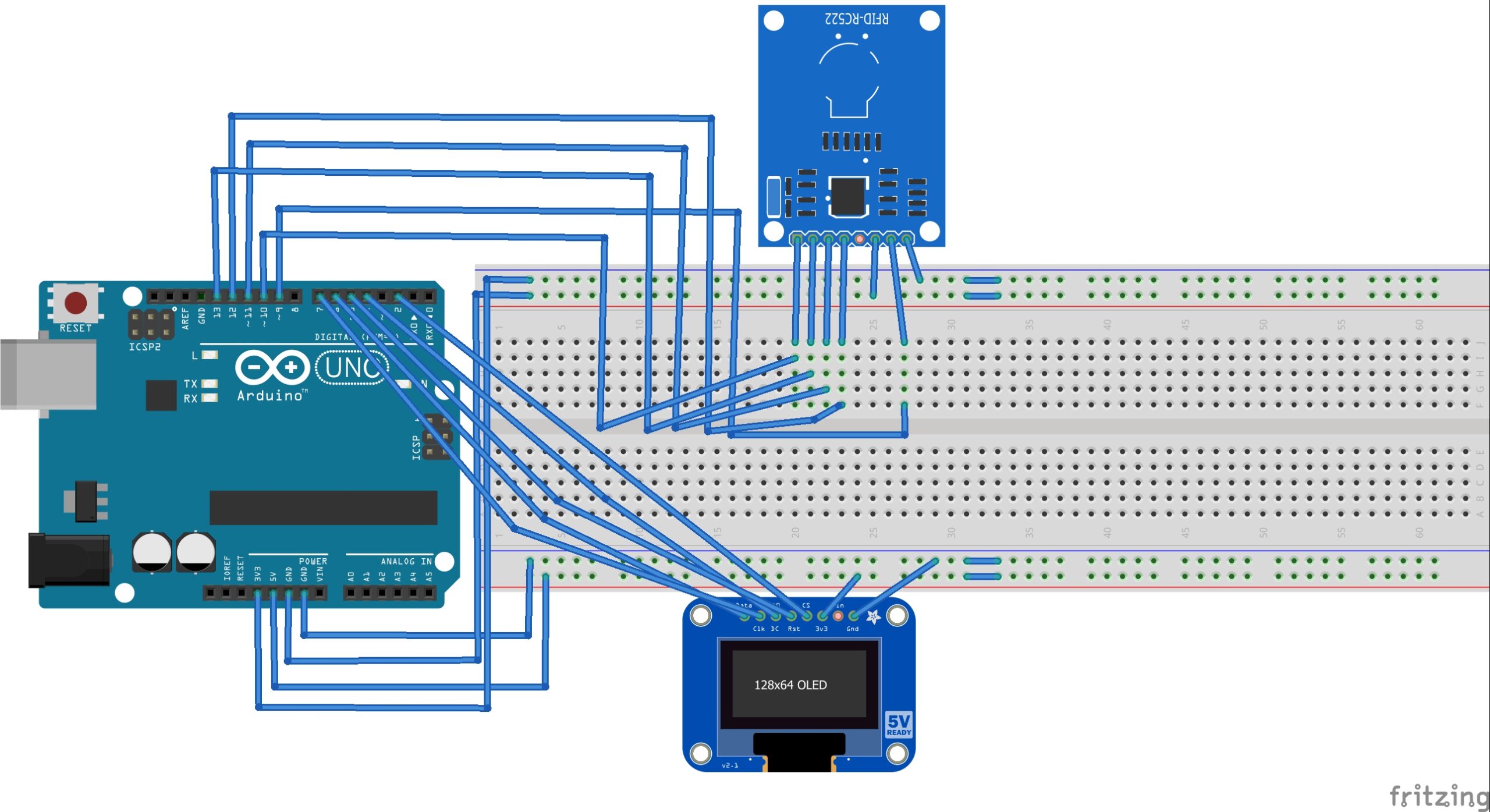
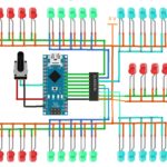
Circuit Diagram of Arduino-based RFID Access System
The locking mechanism can be built in two different ways. A do-it-yourself lock can be designed using a servo motor in one method. If the locking mechanism is built using a servo motor, it requires a PWM pin on Arduino for control.
It is recommended that servo is provided separate power supply using batteries as power fluctuations from the servo motor can damage the Arduino board.
In the second method, the lock can be designed using a solenoid lock. In this case, the lock can be controlled using any GPIO on Arduino via a relay module.
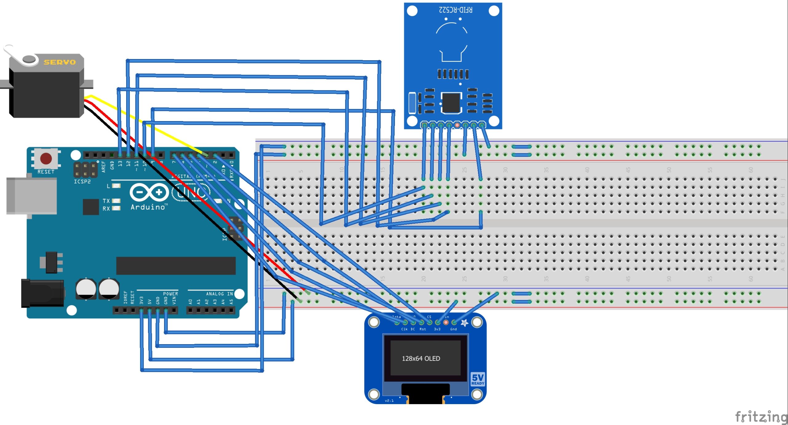
Circuit Diagram of Arduino-based RFID Door Lock with the servo.
The relay itself separates the power supplies of Arduino and the solenoid.
Arduino sketch (RFID Access Control)
How RFID access system works
The RFID reader used to design this door lock is RC522. This RFID reader can read MIFARE and NTAG compatible RFID cards. The RFID cards either have a 7-byte long Unique Identity Number (UID) or 4-byte long Non-Unique Identity Number (NUID). Even if NUID cards are used, there is almost no possibility of getting two cards with the same NUID. The locking systems are designed such that the ID number of scanned cards is not disclosed in the process of access control. Even if the ID of a card is accessed from a different device, it is far from possible to get an RFID card of the same ID number.
When an RFID card is scanned through the RC522, it reads the NUID/UID of the particular card. The scanned NUID is compared against a pre-stored ID number for the door lock system. If the ID of the scanned card matches with the programmed ID, a welcome message is displayed on the OLED display. If the ID of the scanned card does not match with the programmed ID, the door remains unlocked, and a message denying access is displayed on the OLED display. At the same time, the door is unlocked either by rotating the servo in case of DIY servo lock or activating the relay in case of solenoid lock. The lock is programmed to pass access to only one RFID card.
The code
The sketch begins with importing SPI and MFRC522 library for working with the RC522 reader. The library used in this project is Arduino MFRC522 Library from miguelbalboa, available at Github. Download the library as a ZIP file. Navigate to Sketch->Include Library->Add .ZIP Library in Arduino IDE. Select the rfid-master.ZIP, and the library for RC522 is added to the Arduino environment.
This is followed by importing Wire, Adafruit_GFX, and Adafruit_SSD1306 libraries for working with SSD1306 OLED. These libraries can be easily found in the library manager.
Next, constants are defined for circuit connections with the OLED display, and an object of the Adafruit_SSD1306 class is instantiated. The constants for circuit connections with RC522 are defined, and an object of the MFRC522 class is instantiated. A variable to store the MIFARE key is defined. A byte array ‘ nuidPICC[]’ is defined to store 4 bytes of RFID NUID. Variables are declared to store string representations of the NUID in decimal and hexadecimal formats. Similarly, a variable to store a string representation of the MIFARE key is defined. A bitmap is stored in PROGMEM for site loge, and an array is defined for the same.
In the setup() function, the baud rate for serial communication is set to 9600 bps. The OLED display is initialized by calling display.begin(SSD1306_SWITCHCAPVCC) method and display is flashed by calling display.display() method. The SPI protocol is initialized by calling SPI.begin() method. The RFID module initializes the PCD_Init() method on the RFID object. The MIFARE key bytes are set to FF and stored in an upper-case string representation. The MIFARE key is published on the Serial Monitor. The OLED display is cleared, and the site logo is flashed.
In the loop() function, some initial messages are first flashed on the screen. RFID card/key/tag is detected by calling PICC_IsNewCardPresent() method on the RFID object. Next, the card NUID/UID is read by calling the PICC_ReadCardSerial() method on the RFID object. The MIFARE card type is detected using the PICC_GetType(rfid.uid.sak) method and displayed on the Serial Monitor. Next, the individual bytes of the NUID are accessed using the rfid.uid.uidByte[] property. First, the bytes are serialized in decimal format and converted to a string object. The string containing a decimal representation of NUID is published on the Serial Monitor. Next, the bytes are serialized in hexadecimal format and converted to a string object. The string containing a hexadecimal representation of NUID is published on the serial monitor.
The read bytes of NUID are stored in a character array. This character array is compared to a predefined NUID using user-defined compareNUID() function. The function returns a boolean value used to determine access control. If the scanned NUID is matched with the programmed ID, a message granting access is displayed on the OLED screen. If the scanned NUID does not match the programmed ID, a message denying access is displayed on the OLED screen.
The reader is stopped from reading the card by calling PICC_HaltA() method on the rfid object. Finally, the encryption is stopped by calling PCD_StopCrypto1() method on the RFID object.
The loop() function uses two user-defined functions – printtext() and compareNUID(). The printtext() function is defined to display messages on the OLED screen. The compareNUID() function is defined to compare scanned cards with a programmed ID.
Building and controlling locking mechanism
The electronic locking mechanism can be designed in several ways. Here, we discuss two ways. In the first method, we can create a DIY servo lock. The servo remains at zero degrees in an unlocked position and rotates by 90 degrees in the locked position. Its data pin must be connected to an Arduino PWM pin to control the servo. The servo is controlled via pin D3 of the Arduino UNO in the circuit diagram above.
The second method is done by attaching a solenoid lock to the Arduino via a relay module. A 5V relay can be controlled from any GPIO of the Arduino UNO. The pin D3 of Arduino is also a digital input/output, so it can also be used to control the relay.
Arduino sketch for DIY servo lock
Arduino set for solenoid lock
You may also like:


Filed Under: Arduino, Electronic Projects, Featured

Questions related to this article?
👉Ask and discuss on Electro-Tech-Online.com and EDAboard.com forums.
Tell Us What You Think!!
You must be logged in to post a comment.