We learned about different methods and techniques through which individual battery connected in a series combination of multiple batteries can be monitored using microcontrollers. After learning methods and techniques we decided to practically test each method. First we performed practical on monitoring individual batteries connected in series using multiple voltage divider technique with arduino uno. Now tutorial is going with other technique. In this tutorial i am going to to measure individual batteries voltage which are connected in a series string of array by utilizing the double pole single through relay technique.
Arduino Uno series dc battery monitoring using relays
Microcontroller which i selected for this project is arduino uno. Due to its simplicity, pre-build microcontroller board and ready to use libraries in a simple and easy integrated development environment to write and compile code. Four batteries voltages are going to be measured in the tutorial. For four batteries we need four double pole single through(DPST) relays. Dpst relays operate on 9v to 15v. Their coil is energized at 9 volts and make physical contacts. Arduino on the other hand works on 5 volts. Its input/output pins can only source 5 volts and 20 milli ampere of current. This power is not sufficient for driving relays. So i used an external relay driver ic uln2003.
ULN2003 Relay driver
Uln2003 can drive loads from 5 volts to 50 volts at constant 500 milli amperes of current. It has 7 input and 7 output channels. Each channel is composed of a darlington pair of transistors. 5 volts at input can drive medium power load at output. Since arduino sources 5 volts at output it can easily drive uln2003 and ul2003 can output up to 50 volts so it can also easily drive dpst relays. Arduino four digital pins are used to drive four uln2003 channels. Arduino digital pin 4, 5, 6 and 7 are used to drive relays.
To measure the dc battery voltage i used analog channel-0 of arduino. Arduino dc battery monitoring connected in series combination project circuit diagram is given below.
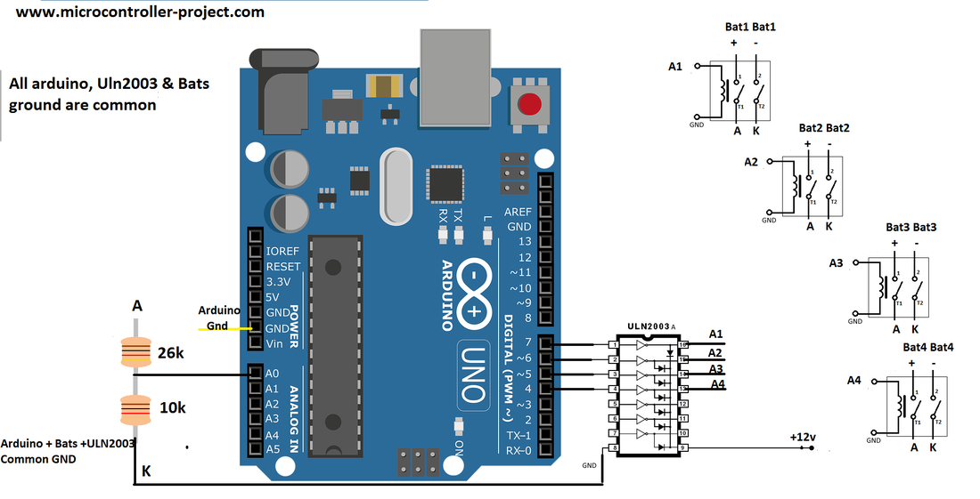
Arduino batteries monitoring in series string using double pole single through relay
Arduino battery monitoring project circuit diagram
Uln2003 output is connected to coil of relays. Uln2003 must be powered by an external source. Its COM pin must be given the voltage which we want to appear on its output channels. I connected a 12 volt source at its COM pin and its ground is connected with 12 volt source ground. Relays coils one side is connected with the output of uln2003 and other is grounded. Batteries are connected across terminals of relays. When you are going to build the above circuit make sure all the connections and wiring are right.
Note: In the above circuit all the grounds are common. 12 volt source, batteries ground and arduino ground must be made common for proper circuit working. Batteries grounds are denoted with K. Normally there is no connection but as soon as the channel closes circuit completes and voltage will appear across the resistor terminals.
Note: In the above circuit all the grounds are common. 12 volt source, batteries ground and arduino ground must be made common for proper circuit working. Batteries grounds are denoted with K. Normally there is no connection but as soon as the channel closes circuit completes and voltage will appear across the resistor terminals.
Arduino battery monitoring voltage divider resistor configuration
In order to understand the resistor voltage divider working and resistance calculation formula. I advice you to please take the below tutorial. It will not only helps you to understand the code below but also give you insight of measuring battery voltage with microcontroller using dpst relays.
Arduino battery monitoring code
Coming to the project code. Code is written in arduino ide. First i defined the analog channel which i am going to use to measure battery voltage. Then i defined the digital pins for relay control. Next comes the ration factor calculation. It is calculated using the formula listed in the tutorial whose link is given above. readVcc function is measuring the actual voltage on which arduino is working. Arduino always is not working on 5 volts. Operating or may be supplying source to arduino is supplying more or less than 5 volts. readVcc function uses macros and measures the operating voltage using internal circuitry. This voltage is used to find the actual and real battery voltage. This function is used in converting the analog channel raw value to actual voltage of battery. Project code is given below.
In the loop function first a single relay is energized as soon as the relay contacts are made battery voltages appears across the voltage divider circuit. Arduino ADC measures the voltage value. Converts raw voltage value to actual battery voltage and closes the relay connection. Next the other relay is energized and same process is repeated for the four batteries. Note that when one relay is energized others are off. If you energize two relays at the same time and their are batteries connected across relay terminals. The two batteries becomes short and your circuit will be fried away. Delay 400 is a necessary delay needed here to properly make and break connections.
Calculated batteries voltages will be displayed on the serial monitor of arduino ide. Once you made circuit just download the code in your arduino and open the serial monitor. You will definitely see batteries voltages displayed on the serial monitor. If voltages are not appearing change the baud rate of serial monitor to 9600 bps. Check for every possible error.
Calculated batteries voltages will be displayed on the serial monitor of arduino ide. Once you made circuit just download the code in your arduino and open the serial monitor. You will definitely see batteries voltages displayed on the serial monitor. If voltages are not appearing change the baud rate of serial monitor to 9600 bps. Check for every possible error.
Download the project code. Folder contains project .ino file. Code is open source you can use and modify it. Avoid shorting the circuit and batteries. It may cause a blast or melt down the battery wires and blow your circuit. Please give us your feed back on the project. If you have any questions or queries write them below in the comments section.
Filed Under: Arduino, Microcontroller Projects

Questions related to this article?
👉Ask and discuss on EDAboard.com and Electro-Tech-Online.com forums.
Tell Us What You Think!!
You must be logged in to post a comment.