In the previous tutorial, the basics of Ethernet technology were discussed. In this tutorial, the Ethernet technology will be used to connect an Arduino board over internet with a PC. The Arduino based IOT device and the PC will be setup to communicate using MQTT protocol via HiveMQ Broker.
An IOT device based on Arduino will be designed in this project. The Arduino will be interfaced with an Arduino Ethernet Shield to connect with a router via Ethernet cable (Cat 5e). The Ethernet modem has TCP/IP stack in itself and MQTT protocol can be implemented over TCP/IP stack. So, an Ethernet modem is used to connect the device to the Internet. The Arduino board will also be interfaced a DHT-11 temperature and humidity sensor and an LED.
The Arduino device will communicate with a remote PC via MQTT broker. So, both the Arduino based device as well as the PC will act as MQTT Clients. The Arduino sketch will be written to read temperature information from the sensor and send it to the MQTT broker. A remote PC which is configured as another MQTT client will then receive the temperature readings and display them on the browser. It will also control the LED interfaced at the Arduino based IOT device by sending appropriate control commands over MQTT protocol. The PC connects with the broker using a chrome add-on – MQTTLens.
Components Required –

Fig. 1: List of components required for MQTT Protocol based Arduino to PC communication
Software Required –
• Arduino IDE
• HiveMQ broker
• MQTTlens (chrome addon)
Block Diagram –

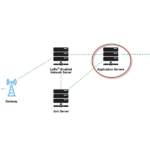
Fig. 2: Overview of MQTT Protocol based Arduino to PC communication
Circuit Connections –
There is an Arduino based temperature monitor designed in this project. The IOT device has been designed by interfacing an Ethernet Shield, DHT-11 Temperature and Humidity sensor and an LED with the Arduino UNO.

Fig. 3: Prototypeof HiveMQ Broker controlled Arduino Ethernet based Temperature Monitor
The device has the following circuit connections –
Arduino UNO – Arduino UNO is one of the most popular prototyping boards. It is an Atmega 328 based controller board which has 14 GPIO pins, 6 PWM pins, 6 Analog inputs and on board UART, SPI and TWI interfaces. The board can communicate with the Arduino Ethernet Shield using the SPI interface. The Atmega 328 is the sitting MCU on the Arduino board. The controller has the following pin configuration –

Fig. 4: Table listing pin configuration of Arduino Uno
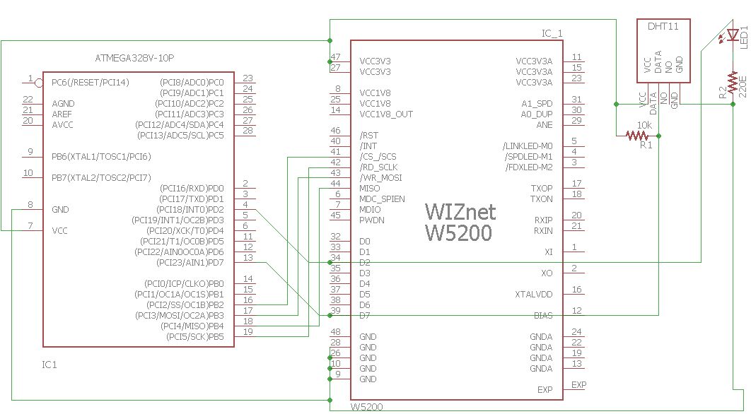
Arduino Ethernet Shield – The Arduino combined with the Arduino Ethernet Shield is called Arduino Ethernet. The Arduino Ethernet shield allows to connect the Arduino to the Internet so that Arduino can become a part of IOT and can communicate with other devices on the same network. It is based on Wiznet W5200 Ethernet chip (according to datasheet). The Ethernet chip provides a network (IP) stack capable of both TCP and UDP. It supports up to four simultaneous socket connections. It uses the SPI (serial peripheral interface) bus to communicate with the Arduino. The pins 10, 11, 12 and 13 of the Ethernet shield are used for SPI communication. The Wiznet 5200 IC has the following pin diagram –

Fig. 5: Pin Diagram of Wiznet W5200 Ethernet IC
For more information on the IC, check out its datasheet –
Wiznet 5200 Datasheet
The Arduino can be connected with the Ethernet shield by placing the Ethernet shield on the top of Arduino UNO or by connecting wires (wherever require!). The Ethernet shield is connected to the router (LAN) via Ethernet cable (Cat 5e). The Arduino is connected to the Ethernet shield as shown in the image below –

Fig. 6: Image of Arduino Ethernet Shield Connected at the top of Arduino UNO
DHT-11 Sensor – DHT-11 is a temperature and humidity sensor. The DHT11 sensor consists of two main components – one is Humidity sensing component and other is NTC temperature sensor (or Thermistor). The Thermistor is actually a variable resistor that changes its resistance with change in temperature. They both sense the temperature and humidity of area and give the output to the IC (which is placed on back side of sensor). The sensor has four pins – VCC, Ground, data Out and NC. The VCC and Ground pins are connected to the common VCC and Ground respectively. The Data Out pin of the sensor is connected to PD7 pin of the Arduino board via 10K pull-up resistor.

Fig. 7: Pin Diagram of DHT-11 Temperature and Humidity Sensor
LED – An LED is interfaced at the PD2 pin of the Arduino board. The LED is connected with its anode connected to the Arduino pin and cathode to the common ground via a 220 ohms series resistor.
On the PC side install the MQTTLens on the chrome browser. MQTTlens supports MQTT protocol and can be used for publishing and subscription of message. PC client should be assigned with unique client ID so that MQTT broker can easily identify which client is publishing and subscribing the topic and payload. Learn more about configuring PC as MQTT Client from the following tutorial –
How to set up PC and Mobile as MQTT Clients
Learn about creating and subscribing topics on HiveMQ broker and publishing messages on them from the following tutorial –
Communication between PC and Mobile using MQTT Protocol Via HiveMQ Broker

Fig. 8: Prototype of HiveMQ Broker controlled Arduino Ethernet based Temperature Monitor
How the circuit works –
The Arduino is connected with the internet router via Ethernet shield and the Ethernet cable. The board is configured as an MQTT Client by its firmware. After loading firmware and circuit connections, the Arduino UNO is ready to receive and send data over MQTT protocol from the available internet router. The PC client is also ready to receive data (temperature and humidity) and send control commands via MQTTLens add-on. The Arduino and PC clients communicate and send messages to each other via a MQTT broker called HiveMQ.
The Arduino client configures as publisher for the topic “current_temeprature” and as subscriber for the topic “Ethernet/LED_status”. The PC client configures as subscriber for the topic “current_temeprature” and as publisher for the topic “Ethernet/LED_status”.
The Arduino reads the temperature and humidity values from the DHT-11 sensor. The DHT11 Temperature and Humidity Sensor is a digital sensor with inbuilt capacitive humidity sensor and Thermistor. It relays a real-time temperature and humidity reading every 2 seconds. The sensor operates on 3.5 to 5.5 V supply and can read temperature between 0° C and 50° C and relative humidity between 20% and 95%. The DHT11 detects water vapors by measuring the electrical resistance between the two electrodes. The humidity sensing component is a moisture holding substrate with electrodes applied to the surface. When water vapors are absorbed by the substrate, ions are released by the substrate which increases the conductivity between the electrodes. The change in resistance between the two electrodes is proportional to the relative humidity. Higher relative humidity decreases the resistance between the electrodes, while lower relative humidity increases the resistance between the electrodes. The DHT11 measures temperature with a surface mounted NTC temperature sensor (Thermistor) built into the unit.
The DHT 11 Sensor sends data in the digital form to the Arduino board on one-wire protocol which must be implemented on firmware side. First the data pin is configured to input and a start signal is sent to it. The start signal comprises of a LOW for 18 milliseconds followed by a HIGH for 20 to 40 microseconds followed by a LOW again for 80 microseconds and a HIGH for 80 microseconds. After sending the start signal, the pin is configured to digital output and 40-bit data comprising of the temperature and humidity reading is latched out. Of the 5-byte data, the first two bytes are integer and decimal part of reading for relative humidity respectively, third and fourth bytes are integer and decimal part of reading for temperature and last one is checksum byte. The one-wire protocol is implemented on the firmware using an open-source library available for Arduino. The Arduino also connects with the Ethernet using an open-source library.
The read temperature and humidity values are sent as messages to the “current_temeprature” topic. The PC client receives messages on the topic and display the reading as message received.
The PC Client after connecting to the internet can publish messages on “Ethernet/LED_status” topic. The PC Client must be operated by a human. On the “Ethernet/LED_status” topic, either ‘on’ or ‘off’ message can be sent. If the message ON is published by the PC client, it will be received by the Arduino client and its firmware code interprets the message to switch on the LED light. If the message OFF is published by the PC client, it will be received by the Arduino client and its firmware code interprets the message to switch off the LED light.
Programming Guide –
The Arduino is programmed to read temperature from the DHT-11 sensor, switch LED on and off and communicate with Ethernet Shield via SPI interface. The MQTT protocol is also implemented within the Arduino code. Arduino Ethernet client is connected to the router’s network by Ethernet shield with a unique MAC ID assigned. The MAC ID (unique ID) and IP address of the Arduino Ethernet client are initialized in the code as follow –
//MAC address of your unique Arduino device
byte mac[]= {0x00, 0xAA, 0xBB, 0xCC, 0xDD, 0xEF};
//IP address of the Arduino Ethernet shield
IPAddressip(192,168,1,110);
The following code is used in the setup() function to initiate the Ethernet communication –
//Start the Ethernet communication
Ethernet.begin(mac, ip);
The Arduino Ethernet client is connected to the HiveMQ broker. The following code in the Arduino sketch is used to define the MQTT broker to which the Arduino has to communicate.
//Initialization of the broker or server domain name
const char* mqtt_server = “broker.mqtt-dashboard.com”;
The Arduino client is connected to the MQTT broker by calling the following function in the setup.
//by setting server & message callback function, the client is ready to use
client.setServer(mqtt_server, 1883);
The PC client is connected to the router’s network wirelessly and also connected to the HiveMQ broker with a unique client ID. When Arduino Ethernet client is connected to the MQTT broker then the client registers the topic “current_temperature” to the MQTT broker and is continuously publishing the real time temperature to the MQTT broker in a repetitive period of 3 seconds. The following code defines to publish topics on the Arduino Client –
//publish the temperature value
client.publish(“current_temperature”, tempC);
The MQTT broker stores the message from the client on the particular topic until and unless no subscriber has subscribed to that topic. The PC client then subscribes to the topic “current_temperature” from the MQTT broker. The MQTT broker checks for the topic, it is requested and then the message with that topic is delivered to the PC client. The PC client continuously receives the temperature sensor data in a repetitive period of 3 seconds until and unless it again unsubscribes to the topic. It is a kind of polling process because once client subscribes to the topic, it continuously receives the message on that topic till it won’t unsubscribe the topic again.
The PC client also registers the topic “Ethernet/LED_status” to the MQTT broker and Arduino Ethernet client subscribes to the topic from the MQTT broker. The following code defines to subscribe topics on the Arduino Client –
//subscribes the topic
client.subscribe(“Ethernet/LED_status”);
The PC client continuously gets the temperature value and it checks for temperature range. When temperature lies above 35 °C, then it publishes the message ‘ON’ on the topic “Ethernet/LED_status” to glow the LED, if temperature lies below 35°c then it publishes the message ‘OFF’ on that topic to off the LED. This is managed by a human operator. The Arduino Ethernet client has subscribed to the topic so it will wait for the message. After receiving message from MQTT broker, it will switch the LED on or off accordingly. The following code is used to control the LED –
//Client receives the message and functions accordingly
voidReceived_Message(char* topic, byte* payload, unsigned int length) {
if((char)payload[0] == ‘o’ && (char)payload[1] == ‘n’) //on
digitalWrite(2, HIGH);
elseif((char)payload[0] == ‘o’ && (char)payload[1] == ‘f’ && (char)payload[2] == ‘f’) //off
digitalWrite(2, LOW);
}
This way the Arduino Ethernet and PC Clients communicate with each other over a communication network via MQTT broker. The Ethernet technology is used to connect the Arduino with the internet network while the PC connects with the router through Wi-Fi. Check out the complete code for designing the project yourself. In the next tutorial, learn about GPRS technology and its use in Internet of Things.
You may also like:


Project Source Code
### //Program to /* * File Name - Device_communication_over_Ethernet_technology_&_MQTT_Protocol.ino * Main Source Code for Publish temperature sensor data to PC client and controlling the LED on Arduino Ethernet client using MQTT * Tested on ATmega328 based Arduino board running on Internal Oscillator at 16MHz */ //Include the Libraries #include//include library for serial communication #include //include library for Ethernet communication #include //include library for MQTT pub sub protocol #include //include library for Temperature sensor #define DHTPIN 7 //DHT temperature sensor connected to pin 7 #define DHTTYPE DHT11 //TYPE of DHT 11 or 22 DHT dht(DHTPIN, DHTTYPE); //Create the instance of DHT #define ledPin 2 //led connected to pin 2 char* tempC; //Variable to hold the temperature of the hall char message_buffer[100]; //initialize a buffer for incoming temperature values byte mac[]= {0x00, 0xAA, 0xBB, 0xCC, 0xDD, 0xEF}; //MAC address of your unique Arduino device IPAddress ip(192,168,1,111); //IP address of the Arduin Etherent shield const char* mqtt_server = "broker.mqtt-dashboard.com"; //The broker or server domain name EthernetClient ethClient; //Create an Ethernet Client class to connect to the MQTT server. PubSubClient client(ethClient); //create the MQTT client objects int timer1_count = 46874; //Timer1-16 bit, Required time = 3 sec, F_CPU= 16MHz void timer1_init() { //Initialize registers TCCR1A = 0; //set entire TCCR1A register to 0 TCCR1B = 0; //set entire TCCR1B register to 0 //Initialize counter TCNT1 = 0; // Set the Compare value that // was calculated for generating a Delay Time period // This updates the temperature after every Delay Time Period OCR1A = timer1_count; //Start timer1 //Set up timer with prescaler = 1024 and CTC mode TCCR1B |= (1 << WGM12)|(1 << CS12)|(1 << CS10); } void setup() { pinMode(ledPin,OUTPUT); //configure the led pin as OUTPUT Serial.begin(115200); //Set the baudrate of ESP8266 to show the process on serial monitor Ethernet.begin(mac, ip); //Start the Ethernet communication dht.begin(); //start the dht sensor to sense temperature timer1_init(); //Initialize the timer function //By setting server and messgae callback function, the client is ready to use client.setServer(mqtt_server, 1883); client.setCallback(Received_Message); } /* * Function name = Received_message * Client receives the message and functions accordingly * Input parameter = Topic, Payload and message length * Output parameter = void */ void Received_Message(char* topic, byte* payload, unsigned int length) { Serial.print("Message arrived ["); Serial.print(topic); Serial.print("] "); for (int i = 0; i < length; i++) { Serial.print((char)payload[i]); } // Handle the message we received // Here, we are only looking at the characters of the received message (payload[0]) // If it is on, turn the led will be on. // If it is off, turn the led will be off. if((char)payload[0] == 'o' && (char)payload[1] == 'n') //on digitalWrite(2,HIGH); else if((char)payload[0] == 'o' && (char)payload[1] == 'f' && (char)payload[2] == 'f') //off digitalWrite(2,LOW); Serial.println(); } /* * Function Name = Reconnect * To establish the connection of Ethernet with MQTT broker * and Will publish and subsribe to the topic */ void reconnect() { // Loop until we're reconnected while (!client.connected()) { Serial.print("Attempting MQTT connection..."); //Attempt to connect if (client.connect("ethClient")) { Serial.println("connected"); //and resubscribe client.subscribe("Ethernet/LED_status"); } else { Serial.print("failed, rc="); Serial.print(client.state()); Serial.println(" try again in 5 seconds"); // Wait 5 seconds before retrying delay(5000); } } } void loop() { //When Ethernet client will be connected to the broker, //then call the function reconnect and publish and subscribe the data from broker. if (!client.connected()) { reconnect(); } client.loop(); float tempF = dht.readTemperature(); //Read the temperature from DHT sensor //There is a useful c function called dtostrf() which will convert a float to a char array so it can then be printed easily. //The format is: dtostrf(floatvar, StringLengthIncDecimalPoint, numVarsAfterDecimal, charbuf); tempC = dtostrf(tempF,5,2,message_buffer); // check whether the flag bit is set // if set, it means that there has been a compare match // and the timer has been cleared // use this opportunity to publish the temperature value if(TIFR1 & (1 << OCF1A)) { //publish the temperature value client.publish("current_temperature", tempC); } // wait! we are not done yet! // clear the flag bit manually since there is no ISR to execute // clear it by writing '1' to it (as per the datasheet) TIFR1 |= (1 << OCF1A); } ###
Circuit Diagrams
Project Video
Filed Under: IoT, IoT tutorials, Tutorials
Filed Under: IoT, IoT tutorials, Tutorials

Questions related to this article?
👉Ask and discuss on EDAboard.com and Electro-Tech-Online.com forums.
Tell Us What You Think!!
You must be logged in to post a comment.