Engineers Garage

  • Electronic Projects & Tutorials
    • Electronic Projects
      • Arduino Projects
      • AVR
      • Raspberry pi
      • ESP8266
      • BeagleBone
      • 8051 Microcontroller
      • ARM
      • PIC Microcontroller
      • STM32
    • Tutorials
      • Audio Electronics
      • Battery Management
      • Brainwave
      • Electric Vehicles
      • EMI/EMC/RFI
      • Hardware Filters
      • IoT tutorials
      • Power Tutorials
      • Python
      • Sensors
      • USB
      • VHDL
    • Circuit Design
    • Project Videos
    • Components
  • Articles
    • Tech Articles
    • Insight
    • Invention Stories
    • How to
    • What Is
  • News
    • Electronic Product News
    • Business News
    • Company/Start-up News
    • DIY Reviews
    • Guest Post
  • Forums
    • EDABoard.com
    • Electro-Tech-Online
    • EG Forum Archive
  • DigiKey Store
    • Cables, Wires
    • Connectors, Interconnect
    • Discrete
    • Electromechanical
    • Embedded Computers
    • Enclosures, Hardware, Office
    • Integrated Circuits (ICs)
    • Isolators
    • LED/Optoelectronics
    • Passive
    • Power, Circuit Protection
    • Programmers
    • RF, Wireless
    • Semiconductors
    • Sensors, Transducers
    • Test Products
    • Tools
  • Learn
    • eBooks/Tech Tips
    • Design Guides
    • Learning Center
    • Tech Toolboxes
    • Webinars & Digital Events
  • Resources
    • Digital Issues
    • EE Training Days
    • LEAP Awards
    • Podcasts
    • Webinars / Digital Events
    • White Papers
    • Engineering Diversity & Inclusion
    • DesignFast
  • Guest Post Guidelines
  • Advertise
  • Subscribe

Arduino water level/quantity/volume indicator/monitor/measurement in water tank

By EG Projects August 28, 2019

In the previous tutorial i discussed how to interface water sensor with arduino? What are arduino water sensor limitations? How to write effective and efficient code for arduino water detector which limits minute calculation errors? At last steps involved in converting analog water reading by arduino in to its equivalent digital form is highlighted.

In this project/tutorial i planned to teach you how to measure the water quantity in tank using arduino water level sensor. As you know arduino water sensor can measure the amount of water its surface is exposed to(How it measure go through previous tutorial). So how can we use this information to measure the whole quantity of water in a given water holding body? Well the whole game revolves around mathematics. I will explain every thing in steps to make it easy for people who are not good in Mathematics. 

Tank water level monitor old techniques

Before microcontrollers era even today if it is not required to measure the quantity to water in a tank and only tank water level is needed to be monitored then cheap digital tank level monitor is used which is usually made at home. This digital meter is usually a string of conducting material(copper etc) wires placed at different levels in a tank. Then an open digital charge wire is placed in water at the bottom of the tank. Water has a property of conducting voltage. So when the water containing digital charge hits wires placed at different heights of a tank it makes a close circuit with the copper wire. This close circuit actives a transistor which consequently switches on an led. If multiple copper wires at different heights in a tank are installed then at the output, water level can be digitally viewed on led string depicting multiple levels of tank. Below image will clear you the concept.          
Water tank level monitor

Copper wired digital tank water level indicator

In the above image it can be seen how copper wires can be used to monitor tank water level. A +5 volt charge is induced in the tank and sensors(copper wires) are placed at different levels of tank. Copper wire other end in connected to base of a NPN transistor. At the end when the charged water hits the copper wire the base of NPN transistor activates the transistor and led glows up. Multiple transistors/led’s makes a cheap water tank level monitor.

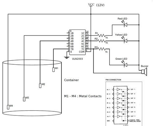
Considering the above copper wire sensors and transistors logic we can take many useful work from the system. For example if the water reaches the bottom of tank then switching on the water pump to refill the tank and if water reaches top switching off the motor. Activating an alarm if water touches dead or full level. See the below picture in which ULN2003 darlington pair ic of transistors is used instead of individual transistors. ULN2003 is a better choice it save space and time to purchase and build the circuit by hand.  

Water tank water level digital indicator - copper wired

Techniques to monitor quantity of water in a tank using Arduino uno

  • Water quantity monitoring using copper wires
  • Water quantity monitoring using Analog to Digital converter(Analog sensor usage)  

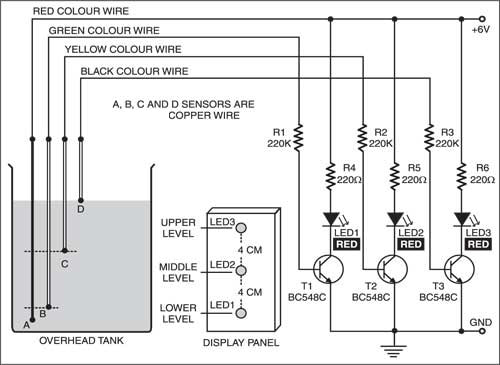
Arduino water quantity monitoring using water level tank indicator and copper wires

The simplest and the easiest way is using the above technique. The only change is to place the copper wires at heights with know volume of water. Now if the water touches the copper wire, read the digital channel and print a message on lcd of quantity or water or do what ever you want.

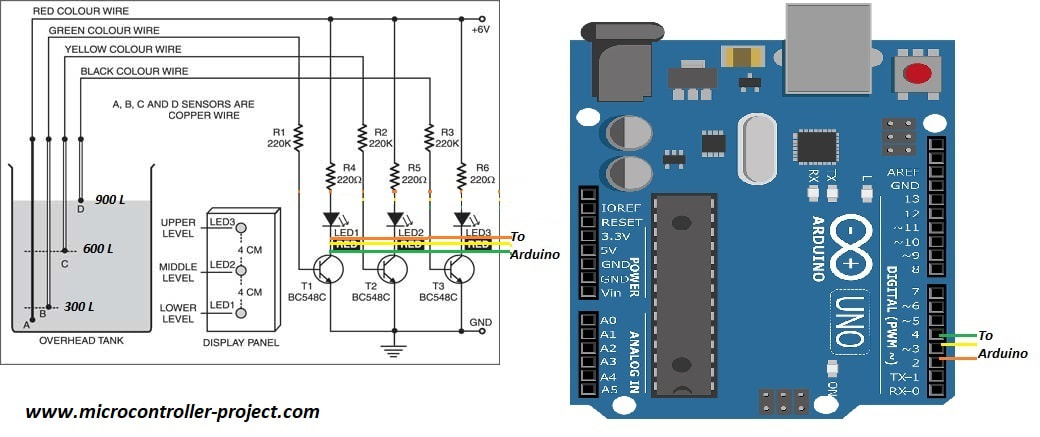
I am going to use the above circuit with three levels/heights. Copper wires are placed at heights with know quantity of water. The output transistor collector side is input to arduino. Three arduino pins are declared as inputs. Now when charged water touches the copper wire the particular led glows up and arduino reads it as a high input. Once arduino finds the particular pin status as high it prints the quantity of water on its serial monitor. Note: The quantity of water at all the three tank levels are known and hard coded in arduino code. Circuit diagram of the project is below.

Copper wired digital water tank quantity/level monitor

Arduino uno tank water level/quantity monitoring

Code of the project is simple. First i defined all the gpios required for the system. Then in the setup() function i declared all the pins as inputs. In the loop function i am checking if a particular pin reaches low state. Normally the input is high but as soon as the water touches the copper wire the base of the npn transistor energizes and current starts flowing from collector to emitter side of transistor which puts our arduino digital input pin in low state or our arduino digital pin is grounded. This change is read by statements in loop function of code and the corresponding quantity of water is displayed on the serial monitor of arduino.

Limitations in the above water quantity in tank monitoring

It can be clearly seen that the above method has many limitations the biggest is that we can not monitor the accurate quantity of water in a tank. Their is always a big margin of error. Suppose if the tank can hold a 1000 liter of water we can not monitor a 1 liter change in water. Even if we want to monitor a change of 100 liters still for that we need to insert 10 copper wires in tank. Also the external hardware(transistors, led’s, resistors etc) for each copper wire increases the cost, power consumption and size of the project. With the same above specification of 1000 liter tank for each 1 liter change monitoring we need 1000 transistors which is not feasible to implement. So we need a better solution to measure the quantity of water in a tank.  

Monitoring water quantity in tank using ADC(Analog to digital converter) of Arduino

In the previous tutorial we discussed that arduino water detector gives an analog reading as output depending on the amount of water its surface is exposed to. So if we put the sensor in water tank in vertical plane and we know about the dimensions of the water tank then we can easily estimate the amount/volume/quantity of water in tank. How is this possible?

Rectangular/Square tank example

Suppose we have a tank whose height is 1 meter and its shape is perfect square or rectangle. We placed the arduino water sensor in this tank in vertical order and lets imagine that the sensor is also 1 meter in length. Now suppose the water in tank is half way. Lets calculate the amount of water in tank manually  

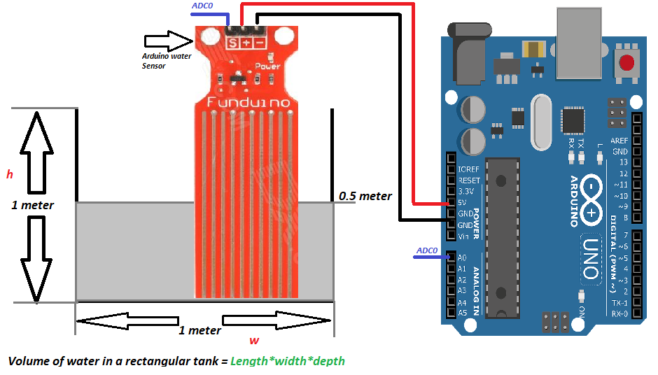
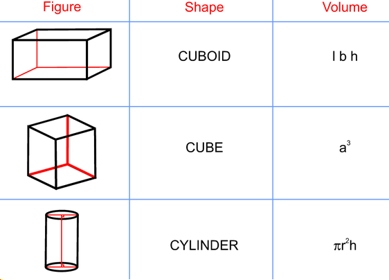
Formula to calculate the volume of water in a rectangular/square tank is given by length x height x depth. 
Since in our case rectangle is a perfect square of 1 meter dimension so 1 x 1 x 1= 1 meter cube.

Now in case if it is half filled. We only need to change the depth variable which is now 1/2. Again calculating the volume of water in tank when it is half filled= 1 x 1 x 1/2 = 0.5 meter cube.

Now see the below diagram in which arduino water detector is placed in tank in vertical order. Recall that arduino water sensor gives an output which is proportional to the amount of water it is exposed to.  

Arduino water detector in a 1 meter tank

Arduino water detector in a 1 meter tank

Arduino analog to digital converter can read voltages from 0 to 5 volts. The output range is from 0 to 5 where 0 represents no voltage and 1024 represents 5 volts. 512 represents 2.5 volts. 

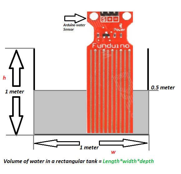
We know that our tank depth is 1 meter and our sensor is also 1 meter in height. Now we want to drive a relation ship between depth of tank and output of water sensor. We know when water reaches in mid of sensor, its output will be 2.5 volts or 512 in integer. Basically we are driving resolution of the water sensor vs the tank height.   

Resolution of water tank vs arduino water sensor

Resolution of water tank vs arduino water sensor

The above value means that 1 degree change in ADC reading of arduino means 0.00097 degree change in depth/height of water in tank. This new height depth value is most important.

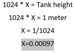
Most Important point:
Now if we take the above scenario in consideration. The water in tank is at height 0.5 meters. At this height the arduino water sensor reads and outputs 512. If we multiply arduino ADC reading(512) with the factor X we can get the volume of water in tank([512 * 0.00097]*1*1 =0.4964 meter cube). We get the correct result. So we can measure the quantity of water in tank with extreme precision using the above technique. Now no matter if the depth of water changes we will get the precise result in all cases we covered the whole range by calculating the X variable. Suppose water reaches 0.25 meters depth arduino will read it as 256. So ([256 * 0.00097]*1*1) = 0.2483 cubic meter

In whole of the above example main variable is X. Once you find the X for a particular tank. Rest of the thing is a piece of cake. Below is the circuit and code of the above project. See the project code how easy it is. 

Arduino water sensor tank water volume monitoring

Arduino water sensor tank water volume monitoring

The above discussed method will perfectly work with following shape of tanks. Tanks whose edges are straight or 90 degree in angle. Only the depth of the shapes is main constraint. 
Arduino tank volume monitoring tanks shapes

Arduino tank volume monitoring tanks shapes

Steps in general to use the above technique

  • Find the length, height, depth of tank. In cylinder find the radius.
  • Calculate variable X using height, depth(discussed above).
  • Calculate new height depth. Actually depth/height of water in tank.
  • Finally calculate volume using the formulas given in above diagram.

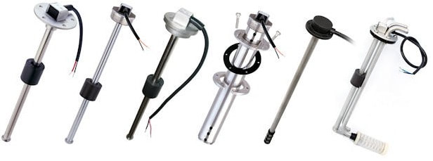
Limitations of the above technique

The first and the only limitation is arduino water sensor height. Arduino water sensor is small in size. Typical height is 10 to 15 cm. This height is not suitable to monitor home water tanks which averagely are 1.5 meters in height.

To overcome this problem commercial analog water monitoring sensors must be used. They are expensive but provide high precision output and their shelf life is also greater then cheap arduino sensors. Typical analog water sensors are shown in below image.  

Analog water sensor for arduino

Analog water sensor can be used with arduino for precise water quantity monitoring and log lasting sensor life

Code/Files


Filed Under: Arduino Projects, Microcontroller Projects


Next Article

← Previous Article
Next Article →

Questions related to this article?
👉Ask and discuss on Electro-Tech-Online.com and EDAboard.com forums.


Tell Us What You Think!! Cancel reply

You must be logged in to post a comment.

EE TECH TOOLBOX

“ee
Tech Toolbox: Internet of Things
Explore practical strategies for minimizing attack surfaces, managing memory efficiently, and securing firmware. Download now to ensure your IoT implementations remain secure, efficient, and future-ready.

EE Learning Center

EE Learning Center
“engineers
EXPAND YOUR KNOWLEDGE AND STAY CONNECTED
Get the latest info on technologies, tools and strategies for EE professionals.

HAVE A QUESTION?

Have a technical question about an article or other engineering questions? Check out our engineering forums EDABoard.com and Electro-Tech-Online.com where you can get those questions asked and answered by your peers!


RSS EDABOARD.com Discussions

  • Input impedance matching network
  • How can I implement real-time digital image stabilization on a dashcam using a DSP?
  • How to preserve hierarchical instance names like \adder_1/U1 in flattened gate-level netlist in Design Compiler?
  • Can anyone provide a guide or tutorial for Candece simulation?
  • Voltage mode pushpull is a nonsense SMPS?

RSS Electro-Tech-Online.com Discussions

  • Can I make two inputs from one??
  • Photo interrupter Connections
  • Is AI making embedded software developers more productive?
  • Why can't I breadboard this oscillator?
  • Cataract Lens Options?

Featured – RPi Python Programming (27 Part)

  • RPi Python Programming 21: The SIM900A AT commands
  • RPi Python Programming 22: Calls & SMS using a SIM900A GSM-GPRS modem
  • RPi Python Programming 23: Interfacing a NEO-6MV2 GPS module with Raspberry Pi
  • RPi Python Programming 24: I2C explained
  • RPi Python Programming 25 – Synchronous serial communication in Raspberry Pi using I2C protocol
  • RPi Python Programming 26 – Interfacing ADXL345 accelerometer sensor with Raspberry Pi

Recent Articles

  • GigaDevice launches GD32C231 MCU series with 48MHz Cortex-M23 core and 64KB Flash
  • Advanced Energy releases 425 W CF-rated medical power supply in 3.5 x 6 x 1.5-inch format”
  • LEM combines shunt and Hall effect sensing in 2000 A current measurement unit
  • What is AWS IoT Core and when should you use it?
  • AC-DC power supply extends voltage range to 800 V DC

EE ENGINEERING TRAINING DAYS

engineering

Submit a Guest Post

submit a guest post
Engineers Garage
  • Analog IC TIps
  • Connector Tips
  • Battery Power Tips
  • DesignFast
  • EDABoard Forums
  • EE World Online
  • Electro-Tech-Online Forums
  • EV Engineering
  • Microcontroller Tips
  • Power Electronic Tips
  • Sensor Tips
  • Test and Measurement Tips
  • 5G Technology World
  • Subscribe to our newsletter
  • About Us
  • Contact Us
  • Advertise

Copyright © 2025 WTWH Media LLC. All Rights Reserved. The material on this site may not be reproduced, distributed, transmitted, cached or otherwise used, except with the prior written permission of WTWH Media
Privacy Policy

Search Engineers Garage

  • Electronic Projects & Tutorials
    • Electronic Projects
      • Arduino Projects
      • AVR
      • Raspberry pi
      • ESP8266
      • BeagleBone
      • 8051 Microcontroller
      • ARM
      • PIC Microcontroller
      • STM32
    • Tutorials
      • Audio Electronics
      • Battery Management
      • Brainwave
      • Electric Vehicles
      • EMI/EMC/RFI
      • Hardware Filters
      • IoT tutorials
      • Power Tutorials
      • Python
      • Sensors
      • USB
      • VHDL
    • Circuit Design
    • Project Videos
    • Components
  • Articles
    • Tech Articles
    • Insight
    • Invention Stories
    • How to
    • What Is
  • News
    • Electronic Product News
    • Business News
    • Company/Start-up News
    • DIY Reviews
    • Guest Post
  • Forums
    • EDABoard.com
    • Electro-Tech-Online
    • EG Forum Archive
  • DigiKey Store
    • Cables, Wires
    • Connectors, Interconnect
    • Discrete
    • Electromechanical
    • Embedded Computers
    • Enclosures, Hardware, Office
    • Integrated Circuits (ICs)
    • Isolators
    • LED/Optoelectronics
    • Passive
    • Power, Circuit Protection
    • Programmers
    • RF, Wireless
    • Semiconductors
    • Sensors, Transducers
    • Test Products
    • Tools
  • Learn
    • eBooks/Tech Tips
    • Design Guides
    • Learning Center
    • Tech Toolboxes
    • Webinars & Digital Events
  • Resources
    • Digital Issues
    • EE Training Days
    • LEAP Awards
    • Podcasts
    • Webinars / Digital Events
    • White Papers
    • Engineering Diversity & Inclusion
    • DesignFast
  • Guest Post Guidelines
  • Advertise
  • Subscribe