Here is a simple project/tutorial in which i will teach you about how to display ASCII characters on character lcd’s. In this tutorial i am using 16×2 lcd. You can use any other size of lcd if you want but be sure to change the lcd initialization statements in the code. Character lcd’s have a built in controller which controls its operations. Usually character lcd’s has HD44780 controller in them. This controller has pre-defined ASCII characters stored in its ROM(read only memory). When we send any character from external microcontroller on lcd data pins and write it to lcd screen, what happens actually is, the character is received by the lcd controller. 16×2 lcd controller then matches the character with its internal ROM characters if matches is found it then displays the character on 16×2 lcd screen.
What can we display on 16×2 lcd?
16×2 lcd is not limited to displaying ASCII characters. Its internal ROM also contains some special Chinese language characters some special shapes. We can display all of them by calling their addresses in ROM.
We can also display custom character’s on 16×2 lcd. By custom characters i mean we can create our own characters and can display them on 16×2 lcd. To display custom characters we utilize the internal CG-RAM(Character generated Random Access Memory) of 16×2 lcd controller. Custom characters generation are not part of this project. I have separate tutorials on them.
16×2 Lcd display character font size
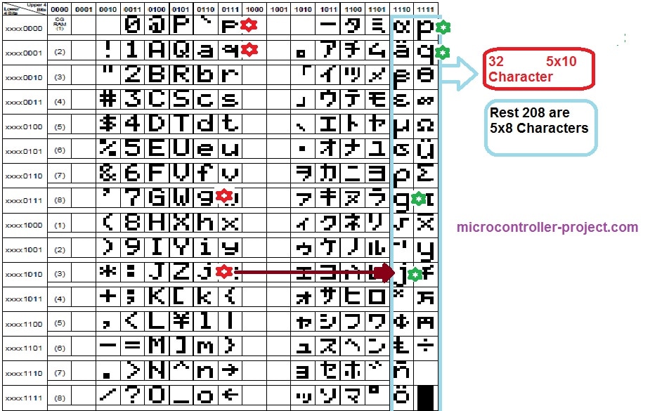
Character lcd’s can display character of size 5×8 and 5×10. In 5×8 dimension 5 represents numbers of rows and 8 represents number of coulombs. Sp in a cube of 5×8 and 5×10 we can display our characters. Normally we display characters in 5×7 font. The 8th coulomb we left is for the cursor movement. 5×10 font is not popular and limited characters can be displayed in 5×10 font. Total 32 characters can be displayed in 5×10 matrix and 208 can be displayed in 5×8 matrix cube. An image of characters with their addresses in ROM of hd44780 lcd controller data sheet is below.
ascii characters displayed on 16×2 lcd using 89c51 microcontroller
Going through the data sheet of HD44780 lcd controller. You will see the character’s that are stored in the ROM(random access memory) of the controller. Character’s with their addresses are listed in the data sheet. You can see the characters and their addresses in the picture given above.
8051 microcontroller ASCII characters display on 16×2 lcd – Project requirements
- 16×2 character lcd
- Breadboard to make circuit
- one 89s51 or 89c51 microcontroller
- A potentiometer to set lcd contrast
- 11.0592 Mhz crystal for clock input
How the project works
I am going to invoke the addresses of each characters/numbers special characters ASCII characters stored in the ROM and they will display on 16×2 lcd screen automatically. On first line of lcd i am printing the decimal value of the ASCII character and on the second line i will display the original ASCII character. whole of the ASCII characters in lcd controller ROM will be displayed on lccd screen one by one. The code is placed in while(1) loop so the process will remain continuous unless the power is cut off.
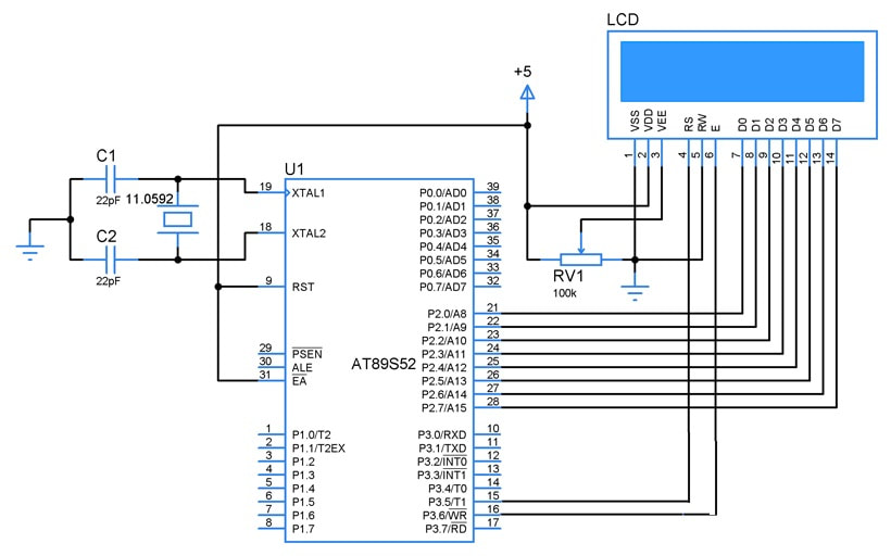
16×2 Lcd ASCII Characters with 8051 microcontroller – Project circuit diagram
Lcd is interfaced in 8-bit mode with 8051 microcontroller. Lcd data pins are connected to port-2 of 89c51 microcontroller. Lcd rs(register select) pin is connected to port-3 pin#5. Lcd rw(read write) pin is connected to port-3 pin#7 and lcd en(enable) pin is connected to port-3 pin#6. Circuit diagram of the project is below.
ASCII characters display on 16×2 lcd with 8051 microcontroller
ASCII characters on lcd – Project code
The code is very simple we hope that you are already familiar with c/c++ programming language. Code is written and compiled in keil uvision ide. First of all the header file re51.h is included. we have to include in our every project which includes 8051 microcontroller in it. Then the lcd rs(register set) rw(read/write) and en(Enable) pins are defined.
Just copy the code and made your circuit burn the code in your microcontroller. Power the circuit and ascii characters will appear on your 16×2 lcd screen. You can also use another size of screen but take care you have to change just only one statement lcdcmd(0x38). If you want to know about the lcd initialization just visit thebelow tutorial.
Download the project code and simulation. Folder contains the keil uvision and proteaus files. Please give us your feed back on the tutorial. In case you have any queries please write them below.
Filed Under: Arduino, Microcontroller Projects

Questions related to this article?
👉Ask and discuss on EDAboard.com and Electro-Tech-Online.com forums.
Tell Us What You Think!!
You must be logged in to post a comment.