In this tutorial i am going to teach you about how to use arduino flow meter to measure the amount of water passing through the water valve. Flow meter is actually a valve. One can control the valve manually and digitally in order to limit the flow of water through the pipe. Normally manual water valve are common but digital and autonomous are also present in market. Digital valves are used in heavy industries like oil and chemicals. In this tutorial we will work with manual valve which has a digital flow meter in it.
Flow meters can be used to measure quantity of water passing through liquid pipes. If water can be monitored so it can also be controlled hence some flow meters have special circuits with actuators through which we can control the water flow. Not only water, flow meters can be used to measure the volume of gas passing through the pipe. With gas volume, flow pressure can also estimated. Major constraints of flow meters are accuracy, precision and resolution. With out accuracy, precision and greater resolution flow meters are of no use.
How water flow meter works?
Flow meters works on the principle of hall effect. What is hall effect? Well hall effect is generation of voltage across a conductor when current is flowing through it and at the same instance it is exposed to a magnetic field. This voltage difference can be measured and calibrated across a scale. The voltage difference depends on the properties of the conductor(metal of which conductor is made).
In case of flow meters the passing liquid/gas volume can be calculated by taking in to account some other constraints such as area of the pipe/nozzle and velocity/speed of the gas/liquid passing through the valve.
Hall effect sensor is composed of two parts. One is stationary. Which is the hall effect sensor it self and the other part is magnet. Magnet is attached to surface which is movable and hall effect sensor is placed perpendicular to the magnetic field of the magnet. The rotating/moving magnet produces a voltage difference across the hall effect sensor. The voltage difference depends on some parameters listed above(area, flow and property of conductor etc) .
In case of water flow meter which is part of this tutorial. We have a fan in flow meter which rotates when water passes through it. With the center point of the fan a magnet is attached which also rotates with the fan. Hall effect sensor is placed above the magnet in perpendicular orientation. The figure below shows the arrangement of all the components in a flow meter.


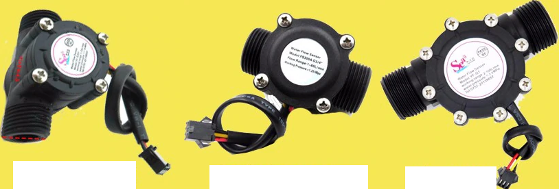
Flow meter used in the tutorial
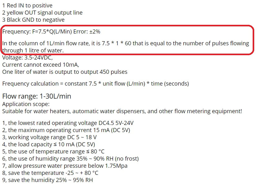
In the above specifications pay special attention to the specs encircled in red box. Lets explain the red colored specs step by step.
The flow sensor outputs pulses on one rotation. We calculate the pulses in a specified amount of time. Pulses represents a quantity or an amount of water is associated with one pulse or with one rotation of fan. Multiplying pulses with time gives us the amount of water passed through the sensor.
For 1 liter per minute= 7.5 * 1 liter * 60 seconds = 450 pulses
The above formula is from the specs. According to the formula 450 pulses represents 1 liter. Where 7.5 represents a constant value which is calculated by the manufacture for particular flow sensor 1 represents water in liters and 60 represent seconds or 1 minute.
If we traverse the formula and try to find the amount of water associated with 1 pulse. It comes out to be.
1 pulse amount = Pulses / 1 liter
1 pulse amount= 450 / 1000 =2.22 mL
Where 1000 mL= 1 liter
So the amount of water associated with 1 pulse is equal to 2.22 milli liters. Now we know that 1 pulse represents 2.2 mL. So if we count the number of pulses in 1 minute(60 seconds) and multiply the pulses with 2.2 ml * 60 seconds, our water in liters per minute L/m is calculated. We can also calculate the liters per second since we have liters per minute.
Note: Frequency of this flow meter is given by 7.5 * Quantity(L/m). Max quantity for this sensor is 30 L/m. We must take in to account the frequency of the sensor for calculating pulses digitally. Our microcontroller must be working on greater frequency then the flow meters.
The above principle can be accomplished with arduino.

Flow meter with arduino – Project code
Though i commented all of the code and every statement clearly reflects its meaning but i found out that some of you still need more explanations. Firstly i named the pin 3 and 7 of arduino as ‘Pulses’ and ‘led’. Then two volatile variables ‘pulsecount‘ and ‘i‘ are used to count pulses and check led status.
You might be wondering how led checks status? Well in the ISR(interrupt service routine) of pin 3 i am toggling the state of led on each pulse. So on one pulse led switches on and on the next one it is switched off. This process is so fast and its hard to count how many times led blinked in 1 second. But you can see the fading-luminous effect with naked eye.
In the setup function i declared the arduino pin 3 as input and activated the internal pull up resistor attached with pin 3. Pull up resistor value is 10 k ohm checked from arduino data sheet. After activating pull up resistor and declaring pin as input i attached interrupt with it. Now pin 3 can count external events. I initialized the external event count on falling edge. Since the pull up resistor is activated so its better to count event on falling edge(HIGH to LOW transition). An ISR(interrupt service routine) is also attached with the pin and i named it as ‘CountPulses‘. Now on every external high to low transition on pin 3 control will jump to isr ‘CountPulses‘. In isr i am incrementing the ‘pulsecount‘ variable. Not only i am incrementing the ‘pulsecount‘ i am also toggling the led in isr. At the end i declared the led pin as output in setup function and i also opened the arduino serial channel at 9600 baud rate.
In the loop function both the volatile variables are initialized to 0. Then arduino interrupts are enabled. Interrupts are enabled for 1 second and then disabled. During this one second number of pulses are counted and are stored in variable ‘pulsecount‘. After disabling interrupts its time to calculate the flow rate.
To calculate the flow rate i used the same formulas highlighted above. I calculated the flow rate in milli liters per minute. You can transform the milli liter per minute to liters per minute by dividing milli liter per minute with 1000. Flow rate is then printed on the arduino serial monitor. You need to open the arduino serial monitor at 9600 bps in order see the flow rate.
Loop function is running infinitely and as long as the power is supplied and sufficient. So the flow rate is calculated continuously. The above code is open source you can modify and use it according to your needs.
Future Work
You can attach a character 16×2 lcd to the system on which the current flow rate is displayed. With some more mathematical calculations you can estimate the amount of water passed through sensor and poured in the water tank. You can close the valve autonomously when a desired amount of water is poured in the tank.
Filed Under: Arduino, Microcontroller Projects

Questions related to this article?
👉Ask and discuss on Electro-Tech-Online.com and EDAboard.com forums.
Tell Us What You Think!!
You must be logged in to post a comment.