Any AVR microcontroller based board which follows the standard Arduino schematic and is flashed with the Arduino bootloader can be called an Arduino board. There is no other tool available which helps in easy prototyping like the Arduino does. The Arduino board has all the required circuitary to get the built-in AVR microcontroller running. When it comes to programming the Arduino board anyone who have basic knowledge of c programming can quickly get started with the Arduino IDE. The tutorial on Getting started with Arduino explains about the steps required to get start with an Arduino board. The Arduino board used in this project is the Arduino pro-mini board and the IDE version of the Arduino is 1.0.3 for windows. The image of the Arduino pro-mini board and the Arduino IDE are shown below;

Fig. 2: Typical Arduino Pro-Mini Board

Fig. 3: Arduino IDE Software Window
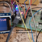
Since the Arduino pro-mini board has no circuitary for interfacing it with the serial port or the USB port of the PC, an external USB to TTL converter board is required to connect it with the PC. This hardware helps in programming the Arduino board and also helps in the serial communication with the USB port of the PC.

Fig. 4: External USB to TTL converter board for programming Arduino and serial communication
It is assumed that the reader has gone through the project how to get started with the Arduino and tried out all the things discussed there. The Arduino IDE has so many functions which help one to interface the four bit LCD module. There are functions to initialize the LCD module and to write character characters in the LCD module. The functions used in the coding of this projects are lcd.begin(), and lcd.print(). The functions are available in the library <LiquidCrystal.h> and one should initialize the library before using those functions.
LiquidCrystallcd()
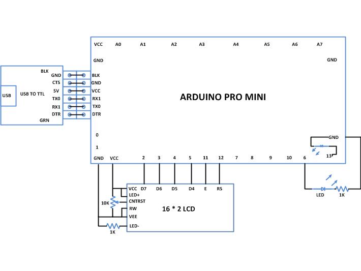
This function should be called to initialize the four bit LCD library and then only the library functions can be called in the code. The function has six parameters which should be provided during a function call as per the circuit connection with the Arduino board and the LCD module. The details of the function parameters are listed in the order below.
")
Fig. 5: Function Parameters Of LiquidCrystallcd()
For example the following statement can be used to initialize an LCD library for the code written for the circuit in which the RS pin is connected to pin12, Enable pin to 11, and D4, D5, D6 and D7 to pins 5, 4, 3 and 2 resepectievely.
lcd.begin()
This function can be used to initialize the LCD module. The first parameter is the number of rows of the LCD module in use and the second parameter is the number of columns. The lcd.begin() function can be used to initialize a 16*2 LCD using the statement;
lcd.begin(16, 2);
The above statement will initialize the 16*2 LCD in four bit mode with two line display mode.
lcd.print()
This function is used to display an ASCII character or string in an LCD screen. If a value is provided as the parameter of the function, it will format that value into displayable string and then display it on the LCD.
The lcd.print() function is analogues to the function Serial.print() discussed with the project on how to do serial debugging with Arduino, how to do serial input and output with Arduino and how send serial data from Arduino.
The lcd.print() function can be used to print a string using the statement as shown below;
lcd.print(“hello world”);
The above statement will print the string “hello world” in the LCD screen. If the value of a variable need to be printed on the LCD screen the same function can be used as it can format a value to the ASCII string representing the value.
lcd.print(100);
In the above statement the value 100 is formatted to string “100” by the lcd.print() function and then displays it on the LCD module.
THE CODE
The code first includes the <LiquidCrystal.h> library which has all the function required to access the LCD module. The 16*2 LCD module used in this project is initialized using the function lcd.begin(). The function lcd.print() is then used to print data on the LCD module.
// include the library code:
#include <LiquidCrystal.h>
// initialize the library with the numbers of the interface pins
LiquidCrystallcd(12, 11, 5, 4, 3, 2);
// give the LED pin a name:
int led = 6;
void setup()
{
// set up the LCD’s number of columns and rows:
lcd.begin(16, 2);
// Print a message to the LCD.
lcd.print(“ENGINEERS GARAGE”);
// initialize the digital pin as an output.
pinMode(led, OUTPUT);
}
void loop()
{
digitalWrite(led, HIGH); // turn the LED on (HIGH is the voltage level)
delay(1000); // wait for a second
digitalWrite(led, LOW); // turn the LED off by making the voltage LOW
delay(1000); // wait for a second
}
The code initializes the module, display a string in the module using the functions available in the <LiquidCrystal.h> library. The code the blinks an LED in an infinite loop using the pinMode () and digitalWrite () functions discussed in the project on how to get started with the Arduino and how to use digital input and output of Arduino.
You may also like:


Project Source Code
### /*============================ EG LABS ===================================// Demonstration on how to use 16x2 LCD display with an arduino board The circuit: The circuit: * LCD RS pin to digital pin 12 * LCD Enable pin to digital pin 11 * LCD D4 pin to digital pin 5 * LCD D5 pin to digital pin 4 * LCD D6 pin to digital pin 3 * LCD D7 pin to digital pin 2 * LCD R/W pin to ground * 10K resistor: * ends to +5V and ground * wiper to LCD pin 3 * LED anode attached to digital output 6 * LED cathode attached to ground through a 1K resistor //============================ EG LABS ===================================*/ // include the library code: #include// initialize the library with the numbers of the interface pins LiquidCrystal lcd(12, 11, 5, 4, 3, 2); // give the LED pin a name: int led = 6; void setup() { // set up the LCD's number of columns and rows: lcd.begin(16, 2); // Print a message to the LCD. lcd.print("ENGINEERS GARAGE"); // initialize the digital pin as an output. pinMode(led, OUTPUT); } void loop() { digitalWrite(led, HIGH); // turn the LED on (HIGH is the voltage level) delay(1000); // wait for a second digitalWrite(led, LOW); // turn the LED off by making the voltage LOW delay(1000); // wait for a second } ###
Circuit Diagrams
Project Components
Project Video
Filed Under: Arduino, Electronic Projects
Filed Under: Arduino, Electronic Projects

Questions related to this article?
👉Ask and discuss on Electro-Tech-Online.com and EDAboard.com forums.
Tell Us What You Think!!
You must be logged in to post a comment.